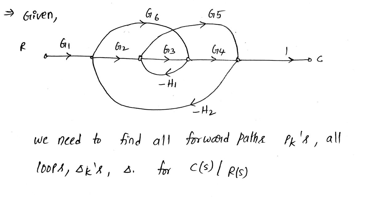
1. You do not need to find the transfer function. 66 Ro G₁ Find all loops, Pk's, Ak's, and A for C(s)/R(s) -62 6 ок-на 65 G4 C
1. You do not need to find the transfer function. 66 Ro G₁ Find all loops, Pk's, Ak's, and A for C(s)/R(s) -62 6 ок-на 65 G4 C
Introductory Circuit Analysis (13th Edition)
13th Edition
ISBN:9780133923605
Author:Robert L. Boylestad
Publisher:Robert L. Boylestad
Chapter1: Introduction
Section: Chapter Questions
Problem 1P: Visit your local library (at school or home) and describe the extent to which it provides literature...
Related questions
Question
100%
Can you show the step please

Transcribed Image Text:**Problem Statement:**
1. (Redacted) Find all loops, \( P_k \)'s, \(\Delta_k\)'s, and \(\Delta\) for \( \frac{C(s)}{R(s)} \).
You do not need to find the transfer function.
**Diagram Explanation:**
The diagram is a block diagram with a flow of signals from left to right.
- **Nodes and Branches:**
- The signal starts at \( R \), which is the reference input.
- It travels through a series of blocks and summing junctions to \( C \), which is the output.
- **Forward Path:**
- The signal passes through transfer functions \( G_1, G_2, G_3, \) and \( G_4 \) sequentially.
- **Feedback Loops:**
- There are three feedback paths shown:
1. The first feedback path starts after \( G_3 \), goes through \( G_5 \), and returns to the input of \( G_2 \).
2. The second feedback path starts after \( G_3 \), goes through \( G_6 \), and returns to the input of \( G_1 \).
3. Two negative feedback paths are labeled with transfer functions \( -H_1 \) and \( -H_2 \). They loop back from different points after the forward elements to earlier points in the diagram.
- **Loops Identified:**
- Loop 1 is the path through \( G_1, G_2, G_5 \).
- Loop 2 is the path through \( G_1, G_6 \).
- Loop 3 involves \( G_2, G_3, -H_1 \).
- Loop 4 comprises \( G_3, G_4 \).
- Loop 5 includes \( G_4, -H_2 \).
Each loop is characterized by the gain product along the loop path. The task involves determining these loops for the use in calculating \( P_k \)'s, \(\Delta_k\)'s, and \(\Delta\), which are key elements in control systems analysis for determining system behavior.
**Further Analysis:**
- To solve the problem, one must list and analyze each loop, utilizing block diagram rules and formulas to compute the necessary parameters without focusing on deriving the overall
Expert Solution
Step 1

Step by step
Solved in 3 steps with 3 images

Knowledge Booster
Learn more about
Need a deep-dive on the concept behind this application? Look no further. Learn more about this topic, electrical-engineering and related others by exploring similar questions and additional content below.Recommended textbooks for you

Introductory Circuit Analysis (13th Edition)
Electrical Engineering
ISBN:
9780133923605
Author:
Robert L. Boylestad
Publisher:
PEARSON

Delmar's Standard Textbook Of Electricity
Electrical Engineering
ISBN:
9781337900348
Author:
Stephen L. Herman
Publisher:
Cengage Learning

Programmable Logic Controllers
Electrical Engineering
ISBN:
9780073373843
Author:
Frank D. Petruzella
Publisher:
McGraw-Hill Education

Introductory Circuit Analysis (13th Edition)
Electrical Engineering
ISBN:
9780133923605
Author:
Robert L. Boylestad
Publisher:
PEARSON

Delmar's Standard Textbook Of Electricity
Electrical Engineering
ISBN:
9781337900348
Author:
Stephen L. Herman
Publisher:
Cengage Learning

Programmable Logic Controllers
Electrical Engineering
ISBN:
9780073373843
Author:
Frank D. Petruzella
Publisher:
McGraw-Hill Education

Fundamentals of Electric Circuits
Electrical Engineering
ISBN:
9780078028229
Author:
Charles K Alexander, Matthew Sadiku
Publisher:
McGraw-Hill Education

Electric Circuits. (11th Edition)
Electrical Engineering
ISBN:
9780134746968
Author:
James W. Nilsson, Susan Riedel
Publisher:
PEARSON

Engineering Electromagnetics
Electrical Engineering
ISBN:
9780078028151
Author:
Hayt, William H. (william Hart), Jr, BUCK, John A.
Publisher:
Mcgraw-hill Education,