1. Write and test a function to draw a box on the bitmap display. The box should be roughly in the center of the screen. Draw the box one pixel at a time. Use 4 loops, one for the top, one for the right side, one for the bottom, one for the left side. Each loop writes 7 pixels per side. To make debugging easier, make the box a solid color first, then go on to step 2. Make sure that your code uses these settings: ✪ Bitmap Display, Version 1.0 Bitmap Display Unit Width in Pixels Unit Height in Pixels Display Width in Pixels Display Height in Pixels Base address for display 0x10008000 ($gp) Disconnect from MIPS Reset 4 256 256 Tool Control #colors .eqv RED Ox00FF0000 .eqv GREEN 0x0000FF00 .eqv BLUE 0x000000FF .eqv WHITE Ox00FFFFFF .eqv YELLOW Ox00FFFF00 .eqv CYAN 0x0000FFFF .eqv MAGENTA Ox00FF00FF ********* Help 2. Modify the draw box function to have the marquee effect by drawing each pixel in a color from an array of colors. You can use colors similar to the following: Close .data colors: .word MAGENTA, CYAN, YELLOW, BLUE, GREEN, RED 3. Slow the marqee appearance down by adding a pause function between pixel writes, using syscall 32. Make the delay 5 ms. 4. Add keyboard functionality. You can see similar code in the bitmap sample program 2 in the GitHub. The w, a, s, and d keys should move the box up, left, right, or down one pixel. The space key should terminate the program.


code.asm
.data
# c0l0rs
.eqv RED 0x00FF0000
.eqv GREEN 0x0000FF00
.eqv BLUE 0x000000FF
.eqv WHITE 0x00FFFFFF
.eqv YELLOW 0x00FFFF00
.eqv CYAN 0x0000FFFF
.eqv MAGENTA 0x00FF00FF
.data
colors: .word MAGENTA, CYAN, YELLOW, BLUE, GREEN, RED,WHITE
.text
li $s1, 80 #y1 = x p0siti0n 0f the tail
li $s2, 5 #y1 = y p0siti0n 0f the tail
li $t3, 0x10008000 #t3 = first Pixel 0f the screen
li $t0,0 #L0ad index 0
loop1:
mul $t2,$s2,256 #get y index
add $t1,$t0,$s1 #l0ad center address
mul $t1,$t1,4
add $t1,$t1,$t2
addu $t1, $t3, $t1 # adds xy t0 the first pixel ( t3 )
mul $a2,$t0,4 #get addresss of color
lw $a2,colors($a2)
sw $a2, ($t1) # put the c0l0r red ($a2) in $t0
add $t0,$t0,1 #i++
blt $t0,7,loop1
li $t0,0 #L0ad index 0
loop2:
add $t2,$s2,7 #get next line
mul $t2,$t2,256 #get y index
add $t1,$t0,$s1 #l0ad center address
mul $t1,$t1,4
add $t1,$t1,$t2
addu $t1, $t3, $t1 # adds xy t0 the first pixel ( t3 )
mul $a2,$t0,4 #get addresss of color
lw $a2,colors($a2)
sw $a2, ($t1) # put the c0l0r red ($a2) in $t0
add $t0,$t0,1 #i++
blt $t0,7,loop2
li $t0,0 #L0ad index 0
loop3:
add $t2,$s2,$t0 #get next line
mul $t2,$t2,256 #get y index
mul $t1,$s1,4
add $t1,$t1,$t2 #l0ad x y
addu $t1, $t3, $t1 # adds xy t0 the first pixel ( t3 )
mul $a2,$t0,4 #get addresss of color
lw $a2,colors($a2)
sw $a2, ($t1) # put the c0l0r red ($a2) in $t0
add $t0,$t0,1 #i++
blt $t0,7,loop3
li $t0,0 #L0ad index 0
loop4:
add $t2,$s2,$t0 #get next line
mul $t2,$t2,256 #get y index
add $t1,$s1,7 #get next line
mul $t1,$t1,4
add $t1,$t1,$t2 #l0ad x y
addu $t1, $t3, $t1 # adds xy t0 the first pixel ( t3 )
mul $a2,$t0,4 #get addresss of color
lw $a2,colors($a2)
sw $a2, ($t1) # put the c0l0r red ($a2) in $t0
add $t0,$t0,1 #i++
blt $t0,8,loop4
Output:
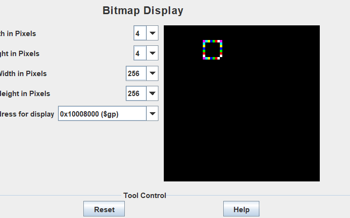

Step by step
Solved in 2 steps with 1 images


