
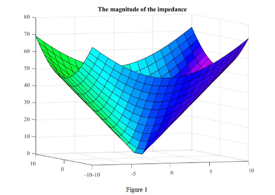
Plot the magnitude of the impedance
Answer to Problem 1P
The magnitude of the impedance as a function of
Explanation of Solution
Given data:
The admittance is,
Calculation:
The admittance is given by,
Substitute
Finding the magnitude of the above function,
Matlab code for the Impedance model:
sigma = linspace(-10,10,21);
omega = linspace(-10,10,21);
[X, Y] = meshgrid(sigma,omega);
Z = abs(2 + 5*X + j*5*Y);
colormap(hsv);
s = [-5 3 8];
surfl(X,Y,Z,s);
view (-20,5)
Matlab output:
The plot for the magnitude of given impedance is shown in Figure 1.
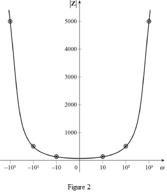
Sketch for
Consider the admittance,
Replace
Taking magnitude,
For various values of
Sketch for
Consider the admittance,
Replace
For various values of
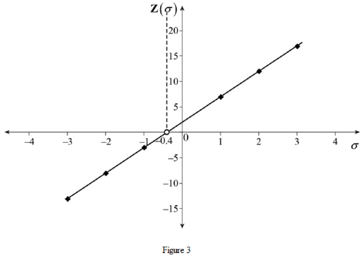
Conclusion:
Thus, the magnitude of the impedance as a function of
Want to see more full solutions like this?
Chapter A8 Solutions
Loose Leaf for Engineering Circuit Analysis Format: Loose-leaf

- Q21arrow_forwardI need help with this problem and an step by step explanation of the solution from the image described below. (Introduction to Signals and Systems)arrow_forwardI need help with this problem and an step by step explanation of the solution from the image described below. (Introduction to Signals and Systems)arrow_forward
- I need help with this problem and an step by step explanation of the solution from the image described below. (Introduction to Signals and Systems)arrow_forwardI need help with this problem and an step by step explanation of the solution from the image described below. (Introduction to Signals and Systems)arrow_forwardI need help with this problem and an step by step explanation of the solution from the image described below. (Introduction to Signals and Systems)arrow_forward
- I need help with this problem and an step by step explanation of the solution from the image described below. (Introduction to Signals and Systems)arrow_forwardImaginary number electrical engineeringarrow_forward3. Describe the function of PLL circuit. 4. Describe the function of bandpass filter. ASK Modulator/Demodulator U1 VD Signal in VT out X1 W R1 VC Carrier in w x2 100K 3 Y1 4 Y2 AD633 Z VR1 10K VR1 Multiplier(1) I U2 Vx out X1 W R3 2 w x2 In2 100K 3 ۲۱ I Y2 AD633 Z VR2 R2 10K C4 100K VR2 Multiplier(2) +5V 200p R5 R6 R101K ww w 2.7K 22K 1N4148 D1 559 VE out D+ In(ac) 6 0H 200p HH 6 VLP out Vo out U3 VR 0.01 0.1u R8 VR3 ww 50K Envelope Detector 10K U3 LF356 VR3 LPF U4Σ LM311 Comparator U5 PLL in CS HH 14 SIGN IN 0.1u 6 CIA PC1OUT 2 PULSES PHASE(2) COMPARATOR OUT 13. C10 HT 150p R16 ww R12 VSO C6 200p VCO OUT 4 IK in R14 C9 18K 10 O w 7 Cle H VLO out 6 15K VCO 150p 06 11 R1 CD4046 VCO IN 9 VR5 1K 12 R2 0.0047u C7 I Demod C8 out 10 SOURCE FOLLOWER R11 100K INH COMP IN 5 3 VR4 +5V+12V GND-12V о HTO 0.1u R13 10K I PL VR5 Figure 18-10 KL-94005 module R15 U6Σ OP37 BPFarrow_forward
- DUC 1. Is the waveform on VT out terminal an ASK modulated signal? TS PROD 2. Is the waveform on VT out terminal an OOK modulated signal? ASK Modulator/Demodulator U1 VD Signal in VT out X1 W R1 VC Carrier in w x2 100K 3 Y1 4 Y2 AD633 Z VR1 10K VR1 Multiplier(1) I U2 Vx out X1 W R3 2 w x2 In2 100K 3 ۲۱ I Y2 AD633 Z VR2 R2 10K C4 100K VR2 Multiplier(2) +5V 200p R5 R6 R101K ww w 2.7K 22K 1N4148 D1 559 VE out D+ In(ac) 6 0H 200p HH 6 VLP out Vo out U3 VR 0.01 0.1u R8 VR3 ww 50K Envelope Detector 10K U3 LF356 VR3 LPF U4Σ LM311 Comparator U5 PLL in CS HH 14 SIGN IN PC1OUT 2 0.1u 6 CIA PULSES PHASE(2) COMPARATOR OUT 13 C10 HT 150p R16 ww R12 VSO 18K C6 200p VCO OUT 4 IK in R14 C9 10 O w H VLO out 6 7 Cle 15K VCO 150p 06 11 R1 CD4046 VCO IN 9 VR5 1K 12 R2 0.0047u C7 I Demod C8 out 10 SOURCE FOLLOWER R11 100K INH COMP IN 5 3 VR4 +5V+12V GND-12V о HTO 0.1u R13 10K I PL Figure 18-10 KL-94005 module VR5 R15 U6Σ OP37 BPFarrow_forwardh e 6. Discuss the relationship between Vx out and VLP out signals. 7. Describe the function of comparator. ASK Modulator/Demodulator U1 VD Signal in VT out X1 W R1 VC Carrier in w x2 100K 3 Y1 4 Y2 AD633 Z VR1 10K VR1 Multiplier(1) I U2 Vx out X1 W R3 2 w x2 In2 100K 3 ۲۱ I Y2 AD633 Z VR2 R2 10K C4 100K VR2 Multiplier(2) +5V 200p R5 R6 R101K ww w 2.7K 22K 1N4148 D1 559 VE out D+ In(ac) 6 0H 200p HH 6 VLP out Vo out U3 VR 0.01 0.1u R8 VR3 ww 50K Envelope Detector 10K U3 LF356 VR3 LPF U4Σ LM311 Comparator U5 PLL in CS HH 14 SIGN IN 0.1u 6 CIA PC1OUT 2 PULSES PHASE(2) COMPARATOR OUT 13. C10 HT 150p R16 ww R12 VSO C6 200p VCO OUT 4 IK in R14 C9 18K 10 O w 7 Cle H VLO out 6 15K VCO 150p 06 11 R1 CD4046 VCO IN 9 VR5 1K 12 R2 0.0047u C7 I Demod C8 out 10 SOURCE FOLLOWER R11 100K INH COMP IN 5 3 VR4 +5V+12V GND-12V о HTO 0.1u R13 10K I PL VR5 Figure 18-10 KL-94005 module R15 U6Σ OP37 BPFarrow_forwardChoose one of the choices indicated in the parentheses such as the following sentences have correct messing What is the main purpose of a communication system? a) To transmit information from one point to another b) To amplify signals for better reception c) To filter out unwanted noise dy To generate carrier waves for modulation 2. What the purpose of the modulator in a communication system? a) To generate the cares wave for modulation b) To convert the information signal to a modulated signal c) To filter out unwanted noise d) To amplify the modulated signal for transmission Which component in an FM transmitter is responsible for generating the carrier signal? a) Mixer b) Modulator c) Demodulator d) Oscillator 4 For a FM signal v(t) 25 cos (15 deviation 10 (3456 4 24669, 7321 7.21284) 117 10 sm 15501). Maximum frequency 5. In an AM receiver, which component is responsible for separating the modulating signal from the received AM signal? a) Mixer b) Modulator c) Demodulator dy…arrow_forward
 Introductory Circuit Analysis (13th Edition)Electrical EngineeringISBN:9780133923605Author:Robert L. BoylestadPublisher:PEARSON
 Delmar's Standard Textbook Of ElectricityElectrical EngineeringISBN:9781337900348Author:Stephen L. HermanPublisher:Cengage Learning
 Programmable Logic ControllersElectrical EngineeringISBN:9780073373843Author:Frank D. PetruzellaPublisher:McGraw-Hill Education
 Fundamentals of Electric CircuitsElectrical EngineeringISBN:9780078028229Author:Charles K Alexander, Matthew SadikuPublisher:McGraw-Hill Education
 Electric Circuits. (11th Edition)Electrical EngineeringISBN:9780134746968Author:James W. Nilsson, Susan RiedelPublisher:PEARSON
 Engineering ElectromagneticsElectrical EngineeringISBN:9780078028151Author:Hayt, William H. (william Hart), Jr, BUCK, John A.Publisher:Mcgraw-hill Education,