
Concept explainers
Videos
(a)
Find the principal moment of inertia at the origin O.
(a)
Answer to Problem 9.179P
The principal moment of inertia at the origin O is
Explanation of Solution
Given information:
The mass of the cylinder is denoted by m.
The length of the circular cylinder is denoted by a.
The diameter OB of the top surface makes
Calculation:
Show the homogeneous circular cylinder as shown in Figure 1.
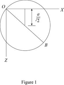
Refer Figure 1.
Refer Figure 9.28.
Apply parallel axis theorem
Show the moment of inertia of the circular cylinder about the y axis as follows:
Show the moment of inertia of the circular cylinder about the x and z axis as follows:
Here, a is the radius of the cylinder and L is the length of the cylinder.
Substitute
The centroidal axis products of inertia are zero due to symmetry.
Write the centroidal locations as measured from the origin O along the x, y and z axis as below;
Express the moment of inertia
Express the moment of inertia
Express the moment of inertia
Show the Equation 9.56 as follows:
Substitute
Substitute
Solve the above Equation and get the values of
Show the principal moment of inertia as follows:
Thus, the principal mass moment of inertia are
(b)
Find the angles made by the principal axis of inertia at O with the coordinate axis.
(b)
Answer to Problem 9.179P
The angles made by the principal axis of inertia at O with the coordinate axis is
Explanation of Solution
Given information:
Consider the direction cosines of each principal axis are denoted by
Calculation:
Refer Part (a).
Show the Equation 9.54 as follows:
Substitute
Modify Equation (3).
Consider
Solve Equation (4).
Add both the Equation in Equation (4).
Substitute
Show the Equation 9.57 as follows:
Substitute
Consider K1.
Substitute
Calculate the value of
Substitute
Show the direction cosines
Conisder K3.
Substitute
Calculate the value of
Substitute
Show the direction cosines
Consider K2.
Show the Equation 9.54b as follows:
Substitute
Refer Equation (3) and (6).
Substitute
Modify above Equations as follows:
Solve Equation (8) and get the value of
Show the Equation 9.57 as follows:
Substitute
Show the direction cosines
Thus, the velocity of the point B is
(c)
Sketch the body and show the orientation of the principal axis of inertia relative to x, y, and z axis.
(c)
Explanation of Solution
Given information:
Calculation:
Refer Part (a) and (b).
Sketch the body and show the orientation of the principal axis of inertia relative to x, y, and z axis as shown in Figure 2.
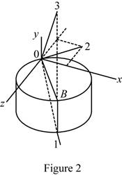
Refer Figure 2.
The principal axis 1 and 3 lies on the vertical plane of symmetry passing through OB.
The principal axis 2 lies in xz plane.
Want to see more full solutions like this?
Chapter 9 Solutions
VECTOR MECHANICS FOR ENGINEERS W/CON >B


- (read image) (answer given)arrow_forward11-5. Compute all the dimensional changes for the steel bar when subjected to the loads shown. The proportional limit of the steel is 230 MPa. 265 kN 100 mm 600 kN 25 mm thickness X Z 600 kN 450 mm E=207×103 MPa; μ= 0.25 265 kNarrow_forwardT₁ F Rd = 0.2 m md = 2 kg T₂ Tz1 Rc = 0.4 m mc = 5 kg m = 3 kgarrow_forward
- 2. Find a basis of solutions by the Frobenius method. Try to identify the series as expansions of known functions. (x + 2)²y" + (x + 2)y' - y = 0 ; Hint: Let: z = x+2arrow_forward1. Find a power series solution in powers of x. y" - y' + x²y = 0arrow_forward3. Find a basis of solutions by the Frobenius method. Try to identify the series as expansions of known functions. 8x2y" +10xy' + (x 1)y = 0 -arrow_forward
- Hello I was going over the solution for this probem and I'm a bit confused on the last part. Can you please explain to me 1^4 was used for the Co of the tubular cross section? Thank you!arrow_forwardBlood (HD = 0.45 in large diameter tubes) is forced through hollow fiber tubes that are 20 µm in diameter.Equating the volumetric flowrate expressions from (1) assuming marginal zone theory and (2) using an apparentviscosity for the blood, estimate the marginal zone thickness at this diameter. The viscosity of plasma is 1.2 cParrow_forwardQ2: Find the shear load on bolt A for the connection shown in Figure 2. Dimensions are in mm Fig. 2 24 0-0 0-0 A 180kN (10 Markarrow_forward
- determine the direction and magnitude of angular velocity ω3 of link CD in the four-bar linkage using the relative velocity graphical methodarrow_forwardFour-bar linkage mechanism, AB=40mm, BC=60mm, CD=70mm, AD=80mm, =60°, w1=10rad/s. Determine the direction and magnitude of w3 using relative motion graphical method. A B 2 3 77777 477777arrow_forwardFour-bar linkage mechanism, AB=40mm, BC=60mm, CD=70mm, AD=80mm, =60°, w1=10rad/s. Determine the direction and magnitude of w3 using relative motion graphical method. A B 2 3 77777 477777arrow_forward
 International Edition---engineering Mechanics: St...Mechanical EngineeringISBN:9781305501607Author:Andrew Pytel And Jaan KiusalaasPublisher:CENGAGE L