
Concept explainers
Videos
9.75 through 9.78 Using the parallel-axis theorem, determine the product of inertia of the area shown with respect to the centroidal x and y axes.
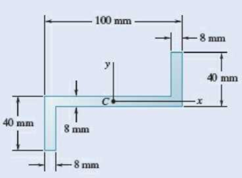
Fig. P9.75
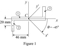
9.82 Determine the moments of inertia and the product of inertia of the area of Prob. 9.75 with respect to new centroidal axes obtained by rotating the x and y axes 45° clockwise.
Find the moment of inertia and product of inertia with respect new centroid axes obtained x and y axes
Answer to Problem 9.82P
The moment of inertia with respect new centroid axes obtained x axes
The moment of inertia with respect new centroid axes obtained y axes
The product of inertia with respect new centroid axes obtained x axes
Explanation of Solution
Calculation:
Refer to problem 9.75.
The product of inertia of the area with respect to x and y axes by using direct parallel axis theorem is
Sketch the rectangular section as shown in Figure 1.
Find the moment of inertia
Here,
Substitute
Find the moment of inertia
Here,
Substitute
Find the total moment of inertia
Substitute
Find the moment of inertia
Substitute
Find the moment of inertia
Substitute
Find the total moment of inertia
Substitute
Find the value of
Find the value of
Find the moment of inertia with respect new centroid axes obtained x axes
Refer to Equation 9.18 in section 9.3B in the textbook.
Substitute
Thus, the moment of inertia with respect new centroid axes obtained x axes
Find the moment of inertia with respect new centroid axes obtained y axes
Refer to Equation 9.19 in section 9.3B in the textbook.
Substitute
Thus, the moment of inertia with respect new centroid axes obtained y axes
Find the product of inertia with respect new centroid axes obtained x and y axes
Substitute
Thus, the product of inertia with respect new centroid axes obtained x axes
Want to see more full solutions like this?
Chapter 9 Solutions
VECTOR MECHANICS FOR ENGINEERS W/CON >B
Additional Engineering Textbook Solutions
Vector Mechanics For Engineers
Fluid Mechanics: Fundamentals and Applications
Elementary Surveying: An Introduction To Geomatics (15th Edition)
Starting Out with Programming Logic and Design (5th Edition) (What's New in Computer Science)
Starting Out with Java: From Control Structures through Data Structures (4th Edition) (What's New in Computer Science)
Automotive Technology: Principles, Diagnosis, And Service (6th Edition) (halderman Automotive Series)


- **Problem 8-45.** The man has a mass of 60 kg and the crate has a mass of 100 kg. If the coefficient of static friction between his shoes and the ground is \( \mu_s = 0.4 \) and between the crate and the ground is \( \mu_c = 0.3 \), determine if the man is able to move the crate using the rope-and-pulley system shown. **Diagram Explanation:** The diagram illustrates a scenario where a man is attempting to pull a crate using a rope-and-pulley system. The setup is as follows: - **Crate (C):** Positioned on the ground with a rope attached. - **Rope:** Connects the crate to a pulley system and extends to the man. - **Pulley on Tree:** The rope runs over a pulley mounted on a tree which redirects the rope. - **Angles:** - The rope between the crate and tree forms a \(30^\circ\) angle with the horizontal. - The rope between the tree and the man makes a \(45^\circ\) angle with the horizontal. - **Man (A):** Pulling on the rope with the intention of moving the crate. This arrangement tests the…arrow_forwardplease solve this problems follow what the question are asking to do please show me step by steparrow_forwardplease first write the line action find the forces and them solve the problem step by steparrow_forward
- please solve this problem what the problem are asking to solve please explain step by step and give me the correct answerarrow_forwardplease help me to solve this problem step by steparrow_forwardplease help me to solve this problem and determine the stress for each point i like to be explained step by step with the correct answerarrow_forward
- please solve this problem for me the best way that you can explained to solve please show me the step how to solvearrow_forwardplese solbe this problem and give the correct answer solve step by step find the forces and line actionarrow_forwardplease help me to solve this problems first write the line of action and them find the forces {fx=0: fy=0: mz=0: and them draw the shear and bending moment diagram. please explain step by steparrow_forward
- please solve this problem step by step like human and give correct answer step by steparrow_forwardPROBLEM 11: Determine the force, P, that must be exerted on the handles of the bolt cutter. (A) 7.5 N (B) 30.0 N (C) 52.5 N (D) 300 N (E) 325 N .B X 3 cm E 40 cm cm F = 1000 N 10 cm 3 cm boltarrow_forwardUsing the moment-area theorems, determine a) the rotation at A, b) the deflection at L/2, c) the deflection at L/4. (Hint: Use symmetry for Part a (θA= - θB, or θC=0), Use the rotation at A for Parts b and c. Note that all deformations in the scope of our topics are small deformation and for small θ, sinθ=θ).arrow_forward
 Elements Of ElectromagneticsMechanical EngineeringISBN:9780190698614Author:Sadiku, Matthew N. O.Publisher:Oxford University Press
 Mechanics of Materials (10th Edition)Mechanical EngineeringISBN:9780134319650Author:Russell C. HibbelerPublisher:PEARSON
 Thermodynamics: An Engineering ApproachMechanical EngineeringISBN:9781259822674Author:Yunus A. Cengel Dr., Michael A. BolesPublisher:McGraw-Hill Education
 Control Systems EngineeringMechanical EngineeringISBN:9781118170519Author:Norman S. NisePublisher:WILEY
 Mechanics of Materials (MindTap Course List)Mechanical EngineeringISBN:9781337093347Author:Barry J. Goodno, James M. GerePublisher:Cengage Learning
 Engineering Mechanics: StaticsMechanical EngineeringISBN:9781118807330Author:James L. Meriam, L. G. Kraige, J. N. BoltonPublisher:WILEY