
Mechanics Of Materials, Si Edition
9th Edition
ISBN: 9789810694364
Author: Russell C Hibbeler
Publisher: Pearson Education
expand_more
expand_more
format_list_bulleted
Concept explainers
Videos
Textbook Question
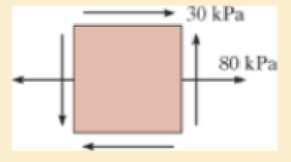
Chapter 9.3, Problem 9.3FP
Also, find the corresponding orientation of the element with respect to the element shown.
Expert Solution & Answer
Want to see the full answer?
Check out a sample textbook solution
Students have asked these similar questions
using the theorem of three moments, find all the moments, I need concise calculations only
Practise question need help on
Can you show explaination and working. The answer from the text book is Q=5.03 X 10^-3
Chapter 9 Solutions
Mechanics Of Materials, Si Edition
Ch. 9.3 - In each case, the state of stress x, y, xy...Ch. 9.3 - Given the state of stress shown on the element,...Ch. 9.3 - Determine the normal stress and shear stress...Ch. 9.3 - Determine the equivalent state of stress on an...Ch. 9.3 - Also, find the corresponding orientation of the...Ch. 9.3 - Determine the equivalent state of stress on an...Ch. 9.3 - Determine the maximum principal stress at point B.Ch. 9.3 - Determine the principal stress at point C.Ch. 9.3 - Prove that the sum of the normal stresses x + y =...Ch. 9.3 - 9-2. The state of stress at a point in a member is...
Ch. 9.3 - Determine the stress components acting on the...Ch. 9.3 - Determine the normal stress and shear stress...Ch. 9.3 - Determine the normal stress and shear stress...Ch. 9.3 - 9-6. Determine the normal stress and shear stress...Ch. 9.3 - 9-7. Determine the normal stress and shear stress...Ch. 9.3 - *9-8. Determine the equivalent state of stress on...Ch. 9.3 - 9-9. Determine the equivalent state of stress on...Ch. 9.3 - Determine the equivalent state of stress on an...Ch. 9.3 - Determine the equivalent slate of stress on an...Ch. 9.3 - *9-12. Determine the equivalent state of stress on...Ch. 9.3 - 9-13. Determine the equivalent state of stress on...Ch. 9.3 - 9-14. The state of stress at a point is shown on...Ch. 9.3 - The state of stress at a point is shown on the...Ch. 9.3 - Determine the equivalent state of stress on an...Ch. 9.3 - Determine the equivalent state of stress on an...Ch. 9.3 - A point on a thin plate is subjected to the two...Ch. 9.3 - Determine the equivalent state of stress on an...Ch. 9.3 - *9-20. Planes AB and BC at a point are subjected...Ch. 9.3 - The stress acting on two planes at a point is...Ch. 9.3 - The grains of wood in the board make an angle of...Ch. 9.3 - The wood beam is subjected to a load of 12 kN. If...Ch. 9.3 - *9-24. The wood beam is subjected to a load of 12...Ch. 9.3 - 9-25. The wooden block will fail if the shear...Ch. 9.3 - 9-26. The bracket is subjected to the force of 3...Ch. 9.3 - 9-27. The bracket is subjected to the force of 3...Ch. 9.3 - 9-28. The 25-mm thick rectangular bar is subjected...Ch. 9.3 - 9-29. The 3-in. diameter shaft is supported by a...Ch. 9.3 - 9-30. The state of stress at a point in a member...Ch. 9.3 - 9-31. Determine the principal stress at point A on...Ch. 9.3 - 9-32. Determine the maximum in-plane shear stress...Ch. 9.3 - 9-33. The clamp bears down on the smooth surface...Ch. 9.3 - 9-34. Determine the principal stress and the...Ch. 9.3 - 9-35. The square steel plate has a thickness of 10...Ch. 9.3 - *9-36. The square steel plate has a thickness of...Ch. 9.3 - The shaft has a diameter d and is subjected to the...Ch. 9.3 - Prob. 9.38PCh. 9.3 - Prob. 9.39PCh. 9.3 - The wide-flange beam is subjected to the 50-kN...Ch. 9.3 - Solve Pro b. 9-40 for point B located on the web...Ch. 9.3 - Prob. 9.42PCh. 9.3 - Prob. 9.43PCh. 9.4 - Use Mohrs circle to determine the normal stress...Ch. 9.4 - Also, find the corresponding orientation of the...Ch. 9.4 - Draw Mohrs circle and determine the principal...Ch. 9.4 - Determine the principal stresses at a point on the...Ch. 9.4 - Determine the principal stresses at point A on the...Ch. 9.4 - Point A is just below the flange.Ch. 9.4 - Solve Prob.93 using Mohrs circle. 93. Determine...Ch. 9.4 - 9-45. Solve Prob. 9-6 using Mohr’s circle.
9-6....Ch. 9.4 - 9-46. Solve Prob. 9-14 using Mohr’s circle.
9-14....Ch. 9.4 - Solve Prob.911 using Mohrs circle. 911. Determine...Ch. 9.4 - *9-48. Solve Prob. 9-12 using Mohr’s...Ch. 9.4 - Solve Prob.916 using Mohrs circle. 916. Determine...Ch. 9.4 - Mohrs circle for the state of stress is shown in...Ch. 9.4 - Prob. 9.51PCh. 9.4 - Prob. 9.52PCh. 9.4 - 9-53. Determine the equivalent state of stress if...Ch. 9.4 - Prob. 9.54PCh. 9.4 - Prob. 9.55PCh. 9.4 - Prob. 9.56PCh. 9.4 - Determine (a) the principal stresses and (b) the...Ch. 9.4 - 9-58. Determine the equivalent state of stress if...Ch. 9.4 - Prob. 9.59PCh. 9.4 - Prob. 9.60PCh. 9.4 - 9-61. Draw Mohr’s circle that describes each of...Ch. 9.4 - The grains of wood in the board make an angle of...Ch. 9.4 - The post is fixed supported at its base and a...Ch. 9.4 - Determine the principal stresses, the maximum...Ch. 9.4 - The thin-walled pipe has an inner diameter of 0.5...Ch. 9.4 - 9-66. Determine the principal stress and maximum...Ch. 9.4 - Prob. 9.67PCh. 9.4 - The rotor shaft of the helicopter is subjected to...Ch. 9.4 - The pedal crank for a bicycle has the cross...Ch. 9.4 - A spherical pressure vessel has an inner radius of...Ch. 9.4 - The cylindrical pressure vessel has an inner...Ch. 9.4 - Determine the normal and shear stresses at point D...Ch. 9.4 - Determine the principal stress at point D, Which...Ch. 9.4 - If the box wrench is subjected to the 50 lb force,...Ch. 9.4 - If the box wrench is subjected to the 50-lb force,...Ch. 9.4 - Prob. 9.76PCh. 9.5 - Draw the three Mohrs circles that describe each of...Ch. 9.5 - Draw the three Mohrs circles that describe the...Ch. 9.5 - 9-79. The stress at a point is shown on the...Ch. 9.5 - Determine the principal stresses and the absolute...Ch. 9.5 - 9-81. The stress at a point is shown on the...Ch. 9.5 - Determine the principal stresses and the absolute...Ch. 9.5 - Determine the principal stresses and the absolute...Ch. 9.5 - Prob. 9.85PCh. 9.5 - Prob. 9.86PCh. 9.5 - 9-87. Determine the principal stresses and...Ch. 9.5 - *9.88. Determine the principal stresses and...Ch. 9 - Prob. 9.89RPCh. 9 - Prob. 9.90RPCh. 9 - Prob. 9.91RPCh. 9 - The steel pipe has an inner diameter of 2.75 in....Ch. 9 - Determine the equivalent state of stress If an...Ch. 9 - The crane is used to support the 350-lb load....Ch. 9 - Determine the equivalent state of stress on an...Ch. 9 - The propeller shaft of the tugboat is subjected to...Ch. 9 - Determine the principal stresses in the box beam...Ch. 9 - Determine (a) the principal stresses and (b) the...Ch. 9 - Determine the stress components acting on the...
Additional Engineering Textbook Solutions
Find more solutions based on key concepts
Porter’s competitive forces model: The model is used to provide a general view about the firms, the competitors...
Management Information Systems: Managing The Digital Firm (16th Edition)
How is the hydrodynamic entry length defined for flow in a pipe? Is the entry length longer in laminar or turbu...
Fluid Mechanics: Fundamentals and Applications
1.2 Explain the difference between geodetic and plane
surveys,
Elementary Surveying: An Introduction To Geomatics (15th Edition)
CONCEPT QUESTIONS
15.CQ3 The ball rolls without slipping on the fixed surface as shown. What is the direction ...
Vector Mechanics for Engineers: Statics and Dynamics
How does a computers main memory differ from its auxiliary memory?
Java: An Introduction to Problem Solving and Programming (8th Edition)
Comprehension Check 7-14
The power absorbed by a resistor can be given by P = I2R, where P is power in units of...
Thinking Like an Engineer: An Active Learning Approach (4th Edition)
Knowledge Booster


Learn more about
Need a deep-dive on the concept behind this application? Look no further. Learn more about this topic, mechanical-engineering and related others by exploring similar questions and additional content below.Similar questions
- practise questionarrow_forwardCan you provide steps and an explaination on how the height value to calculate the Pressure at point B is (-5-3.5) and the solution is 86.4kPa.arrow_forwardPROBLEM 3.46 The solid cylindrical rod BC of length L = 600 mm is attached to the rigid lever AB of length a = 380 mm and to the support at C. When a 500 N force P is applied at A, design specifications require that the displacement of A not exceed 25 mm when a 500 N force P is applied at A For the material indicated determine the required diameter of the rod. Aluminium: Tall = 65 MPa, G = 27 GPa. Aarrow_forward
- Find the equivalent mass of the rocker arm assembly with respect to the x coordinate. k₁ mi m2 k₁arrow_forward2. Figure below shows a U-tube manometer open at both ends and containing a column of liquid mercury of length l and specific weight y. Considering a small displacement x of the manometer meniscus from its equilibrium position (or datum), determine the equivalent spring constant associated with the restoring force. Datum Area, Aarrow_forward1. The consequences of a head-on collision of two automobiles can be studied by considering the impact of the automobile on a barrier, as shown in figure below. Construct a mathematical model (i.e., draw the diagram) by considering the masses of the automobile body, engine, transmission, and suspension and the elasticity of the bumpers, radiator, sheet metal body, driveline, and engine mounts.arrow_forward
- 3.) 15.40 – Collar B moves up at constant velocity vB = 1.5 m/s. Rod AB has length = 1.2 m. The incline is at angle = 25°. Compute an expression for the angular velocity of rod AB, ė and the velocity of end A of the rod (✓✓) as a function of v₂,1,0,0. Then compute numerical answers for ȧ & y_ with 0 = 50°.arrow_forward2.) 15.12 The assembly shown consists of the straight rod ABC which passes through and is welded to the grectangular plate DEFH. The assembly rotates about the axis AC with a constant angular velocity of 9 rad/s. Knowing that the motion when viewed from C is counterclockwise, determine the velocity and acceleration of corner F.arrow_forward500 Q3: The attachment shown in Fig.3 is made of 1040 HR. The static force is 30 kN. Specify the weldment (give the pattern, electrode number, type of weld, length of weld, and leg size). Fig. 3 All dimension in mm 30 kN 100 (10 Marks)arrow_forward
- (read image) (answer given)arrow_forwardA cylinder and a disk are used as pulleys, as shown in the figure. Using the data given in the figure, if a body of mass m = 3 kg is released from rest after falling a height h 1.5 m, find: a) The velocity of the body. b) The angular velocity of the disk. c) The number of revolutions the cylinder has made. T₁ F Rd = 0.2 m md = 2 kg T T₂1 Rc = 0.4 m mc = 5 kg ☐ m = 3 kgarrow_forward(read image) (answer given)arrow_forward
arrow_back_ios
SEE MORE QUESTIONS
arrow_forward_ios
Recommended textbooks for you
 International Edition---engineering Mechanics: St...Mechanical EngineeringISBN:9781305501607Author:Andrew Pytel And Jaan KiusalaasPublisher:CENGAGE L
International Edition---engineering Mechanics: St...
Mechanical Engineering
ISBN:9781305501607
Author:Andrew Pytel And Jaan Kiusalaas
Publisher:CENGAGE L
Dislocations and Plastic Deformation; Author: LearnChemE;https://www.youtube.com/watch?v=cpvTwYAUeA8;License: Standard Youtube License