
STANDALONE CODE MECHANICS OF MATERIALS-M
11th Edition
ISBN: 9780137605200
Author: HIBBELER
Publisher: PEARSON
expand_more
expand_more
format_list_bulleted
Concept explainers
Videos
Textbook Question
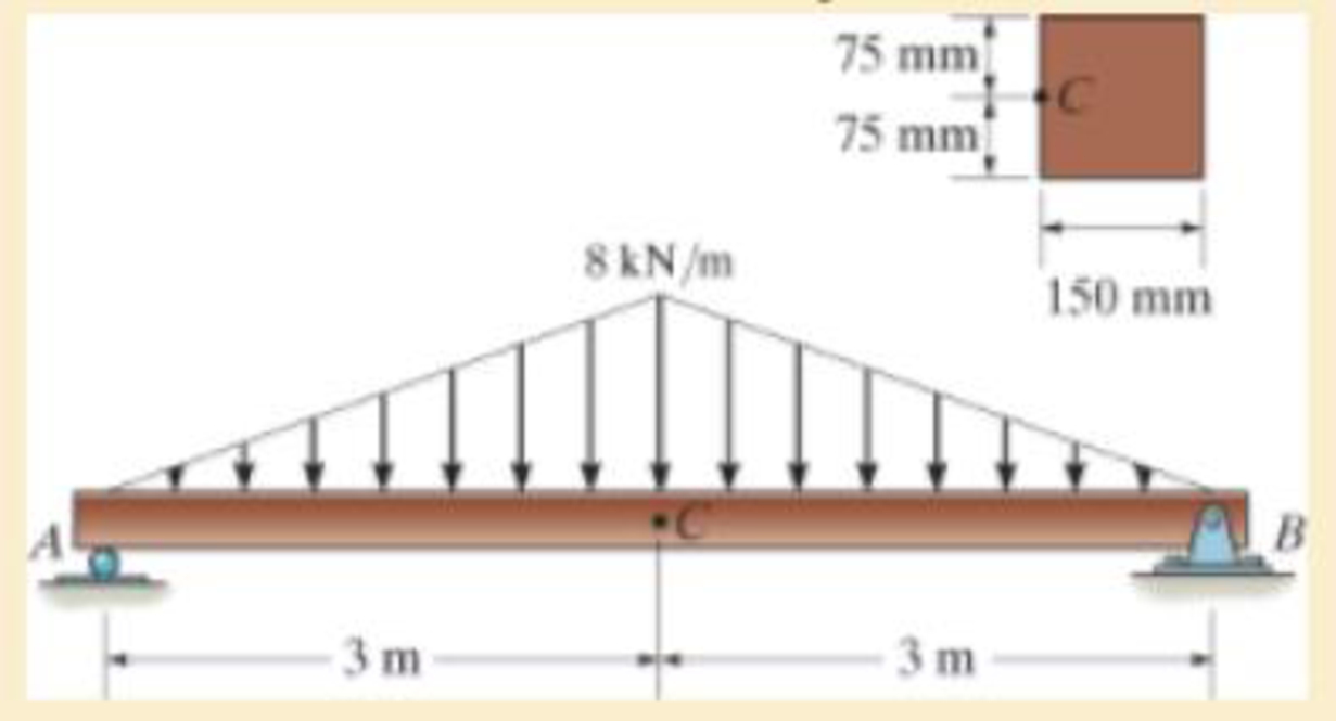
Chapter 9.3, Problem 6FP
Determine the principal stress at point C.
Expert Solution & Answer
Want to see the full answer?
Check out a sample textbook solution
Students have asked these similar questions
Problem 3
For the beam and loading shown, consider section n-n and determine (a) the largest
shearing stress in that section, (b) the shearing stress at point a.
1ft
15 kips 20 kips 15 kips
AITT
in
1
0.6 in.
-10 in.
1 in.
0.375 in.-
2 ft
2ft
2 ft 2ft
10 in.
1
0.6 in.
practice problems want detailed break down
6.105. Determine force P on the cable if the spring is compressed 0.025 m when the mechanism is in the
position shown. The spring has a stiffness of k = 6 kN/m.
E
P
150 mm
D
T
30°
200 mm
200 mm
200 mm
B
800 mm
Chapter 9 Solutions
STANDALONE CODE MECHANICS OF MATERIALS-M
Ch. 9.3 - Determine the normal stress and shear stress...Ch. 9.3 - Determine the equivalent state of stress on an...Ch. 9.3 - Also, find the corresponding orientation of the...Ch. 9.3 - Determine the equivalent state of stress on an...Ch. 9.3 - Determine the maximum principal stress at point B.Ch. 9.3 - Determine the principal stress at point C.Ch. 9.3 - Determine the stress components acting on the...Ch. 9.3 - Solve Prob.99 using the stress transformation...Ch. 9.3 - Determine the stress components acting on the...Ch. 9.3 - Determine the equivalent state of stress on an...
Ch. 9.3 - The stress along two planes at a point is...Ch. 9.3 - The state of stress at a point in a member is...Ch. 9.3 - The wood beam is subjected to a load of 12 kN. If...Ch. 9.3 - The internal loadings at a section of the beam are...Ch. 9.3 - Solve Prob.925 for point B. 925. The internal...Ch. 9.3 - Solve Prob.925 for point C. 925. The internal...Ch. 9.3 - It is subjected to a torque of 12 kip in. and a...Ch. 9.3 - A paper tube is formed by rolling a cardboard...Ch. 9.3 - Solve Prob.931 for the normal stress acting...Ch. 9.3 - Determine the principal stresses in the...Ch. 9.3 - The shaft has a diameter d and is subjected to the...Ch. 9.4 - Use Mohrs circle to determine the normal stress...Ch. 9.4 - Also, find the corresponding orientation of the...Ch. 9.4 - Draw Mohrs circle and determine the principal...Ch. 9.4 - Determine the principal stresses at a point on the...Ch. 9.4 - Determine the principal stresses at point A on the...Ch. 9.4 - Point A is just below the flange.Ch. 9.4 - Mohrs circle for the state of stress is shown in...Ch. 9.4 - Determine (a) the principal stresses and (b) the...Ch. 9.4 - Determine the equivalent state of stress if an...Ch. 9.4 - Draw Mohrs circle that describes each of the...Ch. 9.4 - Draw Mohrs circle trial describes each of the...Ch. 9.4 - Determine (a) the principal stresses and (b) the...Ch. 9.4 - Determine (a) the principal stresses and (b) the...Ch. 9.4 - Draw Mohrs circle that describes each of the...Ch. 9.4 - The grains of wood in the board make an angle of...Ch. 9.4 - A spherical pressure vessel has an inner radius of...Ch. 9.4 - The cylindrical pressure vessel has an inner...Ch. 9.4 - If the box wrench is subjected to the 50 lb force,...Ch. 9.4 - If the box wrench is subjected to the 50-lb force,...Ch. 9.5 - Draw the three Mohrs circles that describe each of...Ch. 9.5 - Draw the three Mohrs circles that describe the...Ch. 9.5 - Determine the principal stresses and the absolute...Ch. 9.5 - The solid shaft is subjected to a torque, bending...Ch. 9.5 - The frame is subjected to a horizontal force and...Ch. 9 - Prob. 1RPCh. 9 - The steel pipe has an inner diameter of 2.75 in....Ch. 9 - Determine the equivalent state of stress If an...Ch. 9 - The crane is used to support the 350-lb load....Ch. 9 - Determine the equivalent state of stress on an...Ch. 9 - The propeller shaft of the tugboat is subjected to...Ch. 9 - Determine the principal stresses in the box beam...Ch. 9 - Determine (a) the principal stresses and (b) the...Ch. 9 - Determine the stress components acting on the...
Additional Engineering Textbook Solutions
Find more solutions based on key concepts
What is an uninitialized variable?
Starting Out with Programming Logic and Design (5th Edition) (What's New in Computer Science)
CONCEPT QUESTIONS
15.CQ3 The ball rolls without slipping on the fixed surface as shown. What is the direction ...
Vector Mechanics for Engineers: Statics and Dynamics
Why is the study of database technology important?
Database Concepts (8th Edition)
17–1C A high-speed aircraft is cruising in still air. How does the temperature of air at the nose of the aircra...
Thermodynamics: An Engineering Approach
How is the hydrodynamic entry length defined for flow in a pipe? Is the entry length longer in laminar or turbu...
Fluid Mechanics: Fundamentals and Applications
How are relationships between tables expressed in a relational database?
Modern Database Management
Knowledge Booster


Learn more about
Need a deep-dive on the concept behind this application? Look no further. Learn more about this topic, mechanical-engineering and related others by exploring similar questions and additional content below.Similar questions
- 6.71. Determine the reactions at the supports A, C, and E of the compound beam. 3 kN/m 12 kN A B CD E -3 m 4 m 6 m 3 m 2 marrow_forwardA countershaft carrying two V-belt pullets is shown in the figure. Pulley A receives power from a motor through a belt with the belt tensions shown. The power is transmitted through the shaft and delivered to the belt on pulley B. Assume the belt tension on the loose side (T1) at B is 30% of the tension on the tight side (T2). (a) Determine the tension (i.e., T₂ and T₁) in the belt on pulley B, assuming the shaft is running at a constant speed. (b) Find the magnitudes of the bearing reaction forces, assuming the bearings act as simple supports. (c) Draw shear-force and bending moment diagrams for the shaft (in XZ and XY plane if needed). (d) Calculate the maximum moments at points A and B respectively and find the point of maximum bending moment (A or B). (e) Find maximum stresses (tensile, compressive, and shear stresses) at the identified point of maximum moment (hint: principal and max shear stresses) 8 dia. 9 400lbf 50lbf 45° 1.5 dia. T₂ B Units in inches T₁ 10 dia.arrow_forwardThe cantilevered bar in the figure is made from a ductile material and is statically loaded with F,, = 200 lbf and Fx = F₂ = 0. Analyze the stress situation in rod AB by obtaining the following information. Note that the stress concentration factors are neglected in the following questions (Kt and Kts=1). (a) Determine the precise location of the critical stress element. (b) Sketch the critical stress element and determine magnitudes and direction for all stresses acting on it. (Transverse shear may only be neglected if you can justify this decision.) (c) For the critical stress element, determine the principal stresses and maximum shear stress. 6 in 1-in dia. B +1- in in 2 in 5 inarrow_forward
- A laminated thick-walled hydraulic cylinder was fabricated by shrink-fitting jacket having an outside diameter of 300mm onto a SS 304 steel tube having an inside diameter of 100mm and an outside diameter of 200mm as shown in the figure. The interference (8) was 0.15mm. When the Young's modulus for both SS304 and 1020 steel is the same as 200GPa, and the Poisson's ratio is also the same as 0.3 for both materials, find the followings. Initially 100 mm Initially 200 mm Initially 300 mm SS 304 1020 steel (a) P; (interfacial contact stress) (b) The maximum stresses (σ, and σ+) in the laminated steel cylinder resulting from the shrink fit.arrow_forwardAuto Controls Design a proportional derivitivecontroller for a plant orsystemthat satisfies the following specifications : 1. is steady-state error is less than 2 % for a ramp input. 2.) Damping ratio (zeta) is greater than 0.7have determined the 3. Once youvalue of kp and kd, then plotthe response of the compensated(with controller) and uncompensated( without the controller, only the plantsystem using MATLAB.arrow_forwardAuto Controls (a) Refer to the above figure .What kind of controller is it ? (b) simplify the block diagramto derive the closed loop transfer function of the system. (C) What are the assumptions thatare needed to make to findthe controller gain ? What arethe value of Kp , Ti and Td ?arrow_forward
- Auto Controls Design a PID controller for thefollowing system so that the modified system satisfies the followingspecifications : 1. settling time ,ts = 1.96 s and % Overshoot Mp = 70.7 % Assume a non-dominant pole at s = -15 to solve the problem The plot the compensated andThen plot the uncompensated system in MATLAB. what can you see from the plot ? what is your observation ?arrow_forwardFourth year Monthly exam\3 2024-2025 Power plant Time: 1 Hr Q1. A gas turbine power plant operates on a modified Brayton cycle consisting of two-stage compression with intercooling to the initial temperature between stages, two-stage expansion with reheating to the maximum cycle temperature, and two regenerative heat exchangers. The following data is given: Inlet air temperature: 300 K Maximum cycle temperature: 1400 K Pressure ratio across each compressor stage: 4 Pressure ratio across each turbine stage: 4 Isentropic efficiency of compressors and turbines: 85% Effectiveness of each regenerator: 80% a) Draw a schematic and T-s diagram of the cycle. b) Determine the thermal efficiency of the cycle. c) Calculate the net specific work output (in kJ/kg). d) Discuss the impact of regenerators on the cycle performance. Examiner Prof. Dr. Adil Al-Kumaitarrow_forwardAuto Controls The figure is a schematic diagram of an aircraft elevator control system. The input to the systemin the deflection angle of the control lever , and the output is the elevator angle phi.show that for each angle theta of the control lever ,there is a corresponding elevator angle phi. Then find Y(s)/theta(s) and simplify the resulting transfer function . Also note from the diagram that y and phi is relatedarrow_forward
- Liquid hexane flows through a counter flow heat exchanger at 5 m3/h as shown in Figure E5.5.The hexane enters the heat exchanger at 90°C. Water, flowing at 5 m3/h, is used to cool the hexane.The water enters the heat exchanger at 15°C. The UA product of the heat exchanger is found to be2.7 kW/K. Determine the outlet temperatures of the hot and cold fluids and the heat transfer ratebetween them using LMTD method.arrow_forwardDetermine the fluid outlet temperatures and the heat transfer rate for the counter flow heatexchanger described in Problem 3 using the ε-NTU model. Assume that the properties can beevaluated at the given fluid inlet temperatures.arrow_forwardSection View - practice Homework 0.5000 3.0000 2,0000 1.0000arrow_forward
arrow_back_ios
SEE MORE QUESTIONS
arrow_forward_ios
Recommended textbooks for you
 Elements Of ElectromagneticsMechanical EngineeringISBN:9780190698614Author:Sadiku, Matthew N. O.Publisher:Oxford University Press
 Mechanics of Materials (10th Edition)Mechanical EngineeringISBN:9780134319650Author:Russell C. HibbelerPublisher:PEARSON
 Thermodynamics: An Engineering ApproachMechanical EngineeringISBN:9781259822674Author:Yunus A. Cengel Dr., Michael A. BolesPublisher:McGraw-Hill Education
 Control Systems EngineeringMechanical EngineeringISBN:9781118170519Author:Norman S. NisePublisher:WILEY
 Mechanics of Materials (MindTap Course List)Mechanical EngineeringISBN:9781337093347Author:Barry J. Goodno, James M. GerePublisher:Cengage Learning
 Engineering Mechanics: StaticsMechanical EngineeringISBN:9781118807330Author:James L. Meriam, L. G. Kraige, J. N. BoltonPublisher:WILEY
Elements Of Electromagnetics
Mechanical Engineering
ISBN:9780190698614
Author:Sadiku, Matthew N. O.
Publisher:Oxford University Press
Mechanics of Materials (10th Edition)
Mechanical Engineering
ISBN:9780134319650
Author:Russell C. Hibbeler
Publisher:PEARSON
Thermodynamics: An Engineering Approach
Mechanical Engineering
ISBN:9781259822674
Author:Yunus A. Cengel Dr., Michael A. Boles
Publisher:McGraw-Hill Education
Control Systems Engineering
Mechanical Engineering
ISBN:9781118170519
Author:Norman S. Nise
Publisher:WILEY
Mechanics of Materials (MindTap Course List)
Mechanical Engineering
ISBN:9781337093347
Author:Barry J. Goodno, James M. Gere
Publisher:Cengage Learning
Engineering Mechanics: Statics
Mechanical Engineering
ISBN:9781118807330
Author:James L. Meriam, L. G. Kraige, J. N. Bolton
Publisher:WILEY
Understanding Stress Transformation and Mohr's Circle; Author: The Efficient Engineer;https://www.youtube.com/watch?v=_DH3546mSCM;License: Standard youtube license