
Concept explainers
Videos
Find the moment of inertia of the shaded area with respect to x axis
Answer to Problem 9.36P
The moment of inertia of the shaded area with respect to x axis
Explanation of Solution
Show the centroidal location of the given section as Figure 1.
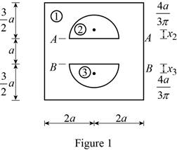
Consider x axis.
Consider the section 1.
Calculate the moment of inertia of the section 1
The expression for the area of the section 1 (A) as follows;
The expression for the centroid of the section 1 (d) as follows;
Calculate the moment of inertia of the section 1
Substitute
The expression for the moment of inertia of the section AA
The section AA and BB compressed of semi-circle.
The expression for the area of the semi-circle (A) as follows;
The expression for the centroid of the semi-circle (d) as follows;
Calculate the moment of inertia of the section 2
Since both sections (2) and (3) are semi-circle which has same moment of inertia.
Substitute
Consider the section 2.
The expression for the centroid of the section 2 (d) from neutral axis as follows;
Calculate the moment of inertia of the section 2
Substitute
Consider the section 3.
The expression for the centroid of the section 3 (d) from neutral axis as follows;
Calculate the moment of inertia of the section 3
Substitute
Calculate the total moment of inertia of the entire section
Substitute
Consider y axis.
Consider the section 1.
Calculate the moment of inertia of the section 1
The expression for the area of the section 1 (A) as follows;
The expression for the centroid of the section 1 (d) as follows;
Calculate the moment of inertia of the section 1
Substitute
Consider the section 2.
Calculate the moment of inertia of the section 2
Substitute
The expression for the area of the semi-circle (A) as follows;
The expression for the centroid of the semi-circle (d) as follows;
Calculate the moment of inertia of the section 1
Substitute
Since the section 2 and section 3 are same. Hence,
Calculate the total moment of inertia of the entire section
Substitute
Therefore, the moment of inertia of the shaded area with respect to x axis
Want to see more full solutions like this?
Chapter 9 Solutions
Vector Mechanics for Engineers: Statics, 11th Edition


- please solve this problems follow what the question are asking to do please show me step by steparrow_forwardplease first write the line action find the forces and them solve the problem step by steparrow_forwardplease solve this problem what the problem are asking to solve please explain step by step and give me the correct answerarrow_forward
- please help me to solve this problem step by steparrow_forwardplease help me to solve this problem and determine the stress for each point i like to be explained step by step with the correct answerarrow_forwardplease solve this problem for me the best way that you can explained to solve please show me the step how to solvearrow_forward
- plese solbe this problem and give the correct answer solve step by step find the forces and line actionarrow_forwardplease help me to solve this problems first write the line of action and them find the forces {fx=0: fy=0: mz=0: and them draw the shear and bending moment diagram. please explain step by steparrow_forwardplease solve this problem step by step like human and give correct answer step by steparrow_forward
- PROBLEM 11: Determine the force, P, that must be exerted on the handles of the bolt cutter. (A) 7.5 N (B) 30.0 N (C) 52.5 N (D) 300 N (E) 325 N .B X 3 cm E 40 cm cm F = 1000 N 10 cm 3 cm boltarrow_forwardUsing the moment-area theorems, determine a) the rotation at A, b) the deflection at L/2, c) the deflection at L/4. (Hint: Use symmetry for Part a (θA= - θB, or θC=0), Use the rotation at A for Parts b and c. Note that all deformations in the scope of our topics are small deformation and for small θ, sinθ=θ).arrow_forwardDistilled water is being cooled by a 20% propylene glycol solution in a 1-1/U counter flow plate and frame heat exchanger. The water enters the heat exchanger at 50°F at a flow rate of 86,000 lbm/h. For safety reasons, the water outlet temperature should never be colder than 35°F. The propylene glycol solution enters the heat exchanger at 28°F with a flow rate of 73,000 lbm/h. The port distances on the heat exchanger are Lv = 35 in and Lh = 18 in. The plate width is Lw = 21.5 2 in. The plate thickness is 0.04 in with a plate pitch of 0.12 in. The chevron angle is 30° and the plate enlargement factor is 1.17. All ports have a 2 in diameter. The fouling factor of the propylene glycol solution can be estimated as 2 ×10⁻⁵ h-ft2-°F/Btu. a. Determine the maximum number of plates the heat exchanger can have while ensuring that the water outlet temperature never drops below 35°F. b. Determine the thermal and hydraulic performance of the heat exchanger with the specified number of plates.…arrow_forward
 Elements Of ElectromagneticsMechanical EngineeringISBN:9780190698614Author:Sadiku, Matthew N. O.Publisher:Oxford University Press
 Mechanics of Materials (10th Edition)Mechanical EngineeringISBN:9780134319650Author:Russell C. HibbelerPublisher:PEARSON
 Thermodynamics: An Engineering ApproachMechanical EngineeringISBN:9781259822674Author:Yunus A. Cengel Dr., Michael A. BolesPublisher:McGraw-Hill Education
 Control Systems EngineeringMechanical EngineeringISBN:9781118170519Author:Norman S. NisePublisher:WILEY
 Mechanics of Materials (MindTap Course List)Mechanical EngineeringISBN:9781337093347Author:Barry J. Goodno, James M. GerePublisher:Cengage Learning
 Engineering Mechanics: StaticsMechanical EngineeringISBN:9781118807330Author:James L. Meriam, L. G. Kraige, J. N. BoltonPublisher:WILEY