Concept explainers
The total exergy destruction for each process of an ideal dual cycle
Answer to Problem 145P
The total exergy destruction in an ideal dual cycle is
Explanation of Solution
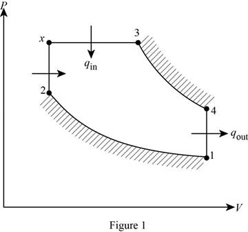
Draw the ideal dual cycle on

Consider, the pressure is
Write the expression of temperature and volume relation for the isentropic compression process 1-2.
Here, compression ratio is r and specific heat ratio is k.
Write the expression of pressure, and volume relation for the isentropic expansion process 1-2.
Write the expression of pressure ratio relation.
Here, pressure ratio is
Write the expression of temperature, and pressure relation for the constant volume heat addition process
Write the expression of temperature, and volume relation for the constant pressure heat addition process
Here, cutoff ratio is
Write the expression of temperature, and volume relation for the constant pressure heat addition process 3-4.
Write the expression to calculate the heat added to the cycle during process
Write the expression to calculate the heat added to the cycle during process
Here, heat input to the process
Write the expression to calculate the heat added to the cycle during process
Here, specific heat at constant pressure is
Write the expression of net heat addition to the cycle
Write the expression for exergy destruction during the process of the cycle.
Here, temperature of the surroundings is
Write the expression of entropy change for the process
Here, specific heat of air at constant volume is
Write the expression for the exergy loss for the isothermal process
Write the expression of entropy change for the isothermal process
Write the expression for the exergy loss for the process
Write the expression of entropy change for the process
Write the expression for the exergy loss for the process
Here, temperature of the sink is
Write the expression to calculate the total in an ideal dual cycle.
Conclusion:
From Table A-1E, “Molar mass, gas constant, and critical-point properties”, obtain the following properties of air at room temperature.
From Table A-2Ea, “Ideal-gas specific heats of various common gases”, obtain the value for gas content
Substitute
Substitute
Substitute
Substitute
Substitute
Substitute
Substitute
Substitute
Substitute
Substitute
Equation (VII).
The exergy loss for the isothermal process 1-2
Here
Substitute
Substitute
Substitute
Substitute
The exergy loss for the isothermal process 3-4
Here,
Substitute
Substitute
During heat rejection process the largest exergy destruction in an ideal dual cycle occur.
Substitute
Thus, the total exergy destruction in an ideal dual cycle is
Want to see more full solutions like this?
Chapter 9 Solutions
CENGEL'S 9TH EDITION OF THERMODYNAMICS:
- Find temperatures STRICTLY USING RITZ APPROXIMATION METHODarrow_forwardSolve this Problem using RITZ APPROXIMATION. STEP BY STEParrow_forwardB/40 The body is constructed of a uniform square plate, a uniform straight rod, a uniform quarter‐circular rod, and a particle (negligible dimensions). If each part has the indicated mass, determine the mass moments of inertia of the body about the x‐, y‐, and z‐axes. Answer Given.arrow_forward
- (read image) Answer:arrow_forward(read image) Answer Givenarrow_forwardB/16. The plane area shown in the top portion of the figure is rotated 180° about the x‐axis to form the body of revolution of mass m shown in the lower portion of the figure. Determine the mass moment of inertia of the body about the x‐axis. Answer Givenarrow_forward
- (read image) Answer:arrow_forward(read image) Answer:arrow_forward2nd Law of Thermodynamics A 1.5-ft3 rigid tank contains saturated refrigerant-134 at 170 psia. Initially, 20 percent of the volume isoccupied by liquid and the rest by vapor. A valve at the top of the tank is now opened, and vapor is allowedto escape slowly from the tank. Heat is transferred to the refrigerant such that the pressure inside the tankremains constant. The valve is closed when the last drop of liquid in the tank is vaporized. Determine thetotal heat transfer for this process.arrow_forward
- Draw the shear and bending-moment diagrams for the beam and loading shown, and determine the maximum normal stress due to bending. 4.8 kips/ft 32 kips B C D E I Hinge 8 ft. 2 ft 5 ft 5 ft W12 x 40arrow_forward2nd Law of Thermodynamics A rigid, insulated tank that is initially evacuated is connected through a valve to the supply line that carrieshelium at 300 kPa and 140◦C. Now the valve is opened, and helium is allowed to flow into the tank until thepressure reaches 300 kPa, at which point the valve is closed. Determine the flow work of the helium in thesupply line and the final temperature of the helium in the tank.arrow_forwardDraw the shear and bending-moment diagrams for the beam and loading shown, and determine the maximum normal stress due to bending. 5 kips 10 kips B I W14 x 22 -5 ft -8 ft 5 ft-arrow_forward
 Elements Of ElectromagneticsMechanical EngineeringISBN:9780190698614Author:Sadiku, Matthew N. O.Publisher:Oxford University Press
 Mechanics of Materials (10th Edition)Mechanical EngineeringISBN:9780134319650Author:Russell C. HibbelerPublisher:PEARSON
 Thermodynamics: An Engineering ApproachMechanical EngineeringISBN:9781259822674Author:Yunus A. Cengel Dr., Michael A. BolesPublisher:McGraw-Hill Education
 Control Systems EngineeringMechanical EngineeringISBN:9781118170519Author:Norman S. NisePublisher:WILEY
 Mechanics of Materials (MindTap Course List)Mechanical EngineeringISBN:9781337093347Author:Barry J. Goodno, James M. GerePublisher:Cengage Learning
 Engineering Mechanics: StaticsMechanical EngineeringISBN:9781118807330Author:James L. Meriam, L. G. Kraige, J. N. BoltonPublisher:WILEY


