
<LCPO> VECTOR MECH,STAT+DYNAMICS
12th Edition
ISBN: 9781265566296
Author: BEER
Publisher: MCG
expand_more
expand_more
format_list_bulleted
Videos
Textbook Question
Chapter 9.1, Problem 9.2P
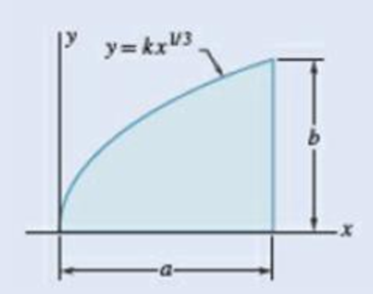
9.1 through 9.4 Determine by direct integration the moment of inertia of the shaded area with respect to y axis.
Expert Solution & Answer
Want to see the full answer?
Check out a sample textbook solution
Students have asked these similar questions
25 mm
Brass core
E
=
105 GPa
0 = 20.9 x 10 °C
PROBLEM 2.49
The aluminum shell is fully bonded to the brass core and the
assembly is unstressed at a temperature of 15°C. Considering only
axial deformations, determine the stress in the aluminum when the
temperature reaches 195°C.
60 mm
Aluminum shell
E = 70 GPa
a = 23.6 × 10°C
This is an old practice exam. The answers are OAB = 19.10 ksi OBC = 2.228 ksi OCD = −2.865 ksi v = 0.2792delta Ltot = 0.01585 in (increase) but why
A random poly(styrene-butadiene) copoly-
mer has a number-average molecular weight of
350,000 g/mol and a degree of polymerization of
5000. Compute the fraction of styrene and buta-
diene repeat units in this copolymer.
H H
| |
-C-C-
방
H
Chapter 9 Solutions
<LCPO> VECTOR MECH,STAT+DYNAMICS
Ch. 9.1 - 9.1 through 9.4 Determine by direct integration...Ch. 9.1 - 9.1 through 9.4 Determine by direct integration...Ch. 9.1 - 9.1 through 9.4 Determine by direct integration...Ch. 9.1 - 9.1 through 9.4 Determine by direct integration...Ch. 9.1 - 9.5 through 9.8 Determine by direct integration...Ch. 9.1 - 9.5 through 9.8 Determine by direct integration...Ch. 9.1 - 9.5 through 9.8 Determine by direct integration...Ch. 9.1 - Prob. 9.8PCh. 9.1 - 9.9 through 9.11 Determine by direct integration...Ch. 9.1 - 9.9 through 9.11 Determine by direct integration...
Ch. 9.1 - Prob. 9.11PCh. 9.1 - Prob. 9.12PCh. 9.1 - 9.12 through 9.14 Determine by direct integration...Ch. 9.1 - 9.12 through 9.14 Determine by direct integration...Ch. 9.1 - Prob. 9.15PCh. 9.1 - Prob. 9.16PCh. 9.1 - Prob. 9.17PCh. 9.1 - Prob. 9.18PCh. 9.1 - Determine the moment of inertia and the radius of...Ch. 9.1 - Prob. 9.20PCh. 9.1 - Determine the polar moment of inertia and the...Ch. 9.1 - Prob. 9.22PCh. 9.1 - Prob. 9.23PCh. 9.1 - 9.23 and 9.24 Determine the polar moment of...Ch. 9.1 - Prob. 9.25PCh. 9.1 - Prob. 9.26PCh. 9.1 - Prob. 9.27PCh. 9.1 - Prob. 9.28PCh. 9.1 - Prob. 9.29PCh. 9.1 - Prove that the centroidal polar moment of inertia...Ch. 9.2 - 9.31 and 9.32 Determine the moment of inertia and...Ch. 9.2 - 9.31 and 9.32 Determine the moment of inertia and...Ch. 9.2 - 9.33 and 9.34 Determine the moment of inertia and...Ch. 9.2 - 9.33 and 9.34 Determine the moment of inertia and...Ch. 9.2 - Determine the moments of inertia of the shaded...Ch. 9.2 - Determine the moments of inertia of the shaded...Ch. 9.2 - Prob. 9.37PCh. 9.2 - Prob. 9.38PCh. 9.2 - Prob. 9.39PCh. 9.2 - Prob. 9.40PCh. 9.2 - 9.41 through 9.44 Determine the moments of inertia...Ch. 9.2 - 9.41 through 9.44 Determine the moments of inertia...Ch. 9.2 - Prob. 9.43PCh. 9.2 - Prob. 9.44PCh. 9.2 - 9.45 and 9.46 Determine the polar moment of...Ch. 9.2 - Prob. 9.46PCh. 9.2 - 9.47 and 9.48 Determine the polar moment of...Ch. 9.2 - 9.47 and 9.48 Determine the polar moment of...Ch. 9.2 - To form a reinforced box section, two rolled W...Ch. 9.2 - Two channels are welded to a d 12-in. steel plate...Ch. 9.2 - Prob. 9.51PCh. 9.2 - Two 20-mm steel plates are welded to a rolled S...Ch. 9.2 - A channel and a plate are welded together as shown...Ch. 9.2 - Prob. 9.54PCh. 9.2 - Two L76 76 6.4-mm angles are welded to a C250 ...Ch. 9.2 - Prob. 9.56PCh. 9.2 - Prob. 9.57PCh. 9.2 - 9.57 and 9.58 The panel shown forms the end of a...Ch. 9.2 - Prob. 9.59PCh. 9.2 - Prob. 9.60PCh. 9.2 - Prob. 9.61PCh. 9.2 - Prob. 9.62PCh. 9.2 - Prob. 9.63PCh. 9.2 - Prob. 9.64PCh. 9.2 - Prob. 9.65PCh. 9.2 - Prob. 9.66PCh. 9.3 - 9.67 through 9.70 Determine by direct integration...Ch. 9.3 - 9.67 through 9.70 Determine by direct integration...Ch. 9.3 - 9.67 through 9.70 Determine by direct integration...Ch. 9.3 - Prob. 9.70PCh. 9.3 - Prob. 9.71PCh. 9.3 - Prob. 9.72PCh. 9.3 - Prob. 9.73PCh. 9.3 - 9.71 through 9.74 Using the parallel-axis theorem,...Ch. 9.3 - Prob. 9.75PCh. 9.3 - 9.75 through 9.78 Using the parallel-axis theorem,...Ch. 9.3 - Prob. 9.77PCh. 9.3 - Prob. 9.78PCh. 9.3 - Determine for the quarter ellipse of Prob. 9.67...Ch. 9.3 - Determine the moments of inertia and the product...Ch. 9.3 - Determine the moments of inertia and the product...Ch. 9.3 - 9.75 through 9.78 Using the parallel-axis theorem,...Ch. 9.3 - Determine the moments of inertia and the product...Ch. 9.3 - Determine the moments of inertia and the product...Ch. 9.3 - Prob. 9.85PCh. 9.3 - 9.86 through 9.88 For the area indicated,...Ch. 9.3 - Prob. 9.87PCh. 9.3 - Prob. 9.88PCh. 9.3 - Prob. 9.89PCh. 9.3 - 9.89 and 9.90 For the angle cross section...Ch. 9.4 - Using Mohrs circle, determine for the quarter...Ch. 9.4 - Using Mohrs circle, determine the moments of...Ch. 9.4 - Prob. 9.93PCh. 9.4 - Using Mohrs circle, determine the moments of...Ch. 9.4 - Using Mohrs circle, determine the moments of...Ch. 9.4 - Using Mohrs circle, determine the moments of...Ch. 9.4 - For the quarter ellipse of Prob. 9.67, use Mohrs...Ch. 9.4 - 9.98 though 9.102 Using Mohrs circle, determine...Ch. 9.4 - Prob. 9.99PCh. 9.4 - 9.98 though 9.102 Using Mohrs circle, determine...Ch. 9.4 - Prob. 9.101PCh. 9.4 - Prob. 9.102PCh. 9.4 - Prob. 9.103PCh. 9.4 - 9.104 and 9.105 Using Mohrs circle, determine the...Ch. 9.4 - 9.104 and 9.105 Using Mohrs circle, determine the...Ch. 9.4 - For a given area, the moments of inertia with...Ch. 9.4 - it is known that for a given area Iy = 48 106 mm4...Ch. 9.4 - Prob. 9.108PCh. 9.4 - Prob. 9.109PCh. 9.4 - Prob. 9.110PCh. 9.5 - A thin plate with a mass m is cut in the shape of...Ch. 9.5 - A ring with a mass m is cut from a thin uniform...Ch. 9.5 - A thin elliptical plate has a mass m. Determine...Ch. 9.5 - The parabolic spandrel shown was cut from a thin,...Ch. 9.5 - Prob. 9.115PCh. 9.5 - Fig. P9.115 and P9.116 9.116 A piece of thin,...Ch. 9.5 - A thin plate of mass m is cut in the shape of an...Ch. 9.5 - Fig. P9.117 and P9.118 9.118 A thin plate of mass...Ch. 9.5 - Determine by direct integration the mass moment of...Ch. 9.5 - The area shown is revolved about the x axis to...Ch. 9.5 - The area shown is revolved about the x axis to...Ch. 9.5 - Determine by direct integration the mass moment of...Ch. 9.5 - Fig. P9.122 and P9.123 9.123 Determine by direct...Ch. 9.5 - Prob. 9.124PCh. 9.5 - Prob. 9.125PCh. 9.5 - Prob. 9.126PCh. 9.5 - Prob. 9.127PCh. 9.5 - Prob. 9.128PCh. 9.5 - Prob. 9.129PCh. 9.5 - Knowing that the thin cylindrical shell shown has...Ch. 9.5 - A circular hole of radius r is to be drilled...Ch. 9.5 - The cups and the arms of an anemometer are...Ch. 9.5 - Prob. 9.133PCh. 9.5 - Determine the mass moment of inertia of the 0.9-lb...Ch. 9.5 - Prob. 9.135PCh. 9.5 - Prob. 9.136PCh. 9.5 - A 2-mm thick piece of sheet steel is cut and bent...Ch. 9.5 - A section of sheet steel 0.03 in. thick is cut and...Ch. 9.5 - A corner reflector for tracking by radar has two...Ch. 9.5 - A farmer constructs a trough by welding a...Ch. 9.5 - The machine element shown is fabricated from...Ch. 9.5 - Determine the mass moments of inertia and the...Ch. 9.5 - Determine the mass moment of inertia of the steel...Ch. 9.5 - Prob. 9.144PCh. 9.5 - Determine the mass moment of inertia of the steel...Ch. 9.5 - Aluminum wire with a weight per unit length of...Ch. 9.5 - The figure shown is formed of 18-in.-diameter...Ch. 9.5 - A homogeneous wire with a mass per unit length of...Ch. 9.6 - Determine the mass products of inertia Ixy, Iyz,...Ch. 9.6 - Determine the mass products of inertia Ixy, Iyz,...Ch. 9.6 - Determine the mass products of inertia Ixy, Iyz,...Ch. 9.6 - Determine the mass products of inertia Ixy, Iyz,...Ch. 9.6 - 9.153 through 9.156 A section of sheet steel 2 mm...Ch. 9.6 - Prob. 9.154PCh. 9.6 - Prob. 9.155PCh. 9.6 - 9.153 through 9.156 A section of sheet steel 2 mm...Ch. 9.6 - Prob. 9.157PCh. 9.6 - Prob. 9.158PCh. 9.6 - Prob. 9.159PCh. 9.6 - Prob. 9.160PCh. 9.6 - Prob. 9.161PCh. 9.6 - For the homogeneous tetrahedron of mass m shown,...Ch. 9.6 - Prob. 9.163PCh. 9.6 - Prob. 9.164PCh. 9.6 - Prob. 9.165PCh. 9.6 - Determine the mass moment of inertia of the steel...Ch. 9.6 - Prob. 9.167PCh. 9.6 - Prob. 9.168PCh. 9.6 - Prob. 9.169PCh. 9.6 - 9.170 through 9.172 For the wire figure of the...Ch. 9.6 - Prob. 9.171PCh. 9.6 - Prob. 9.172PCh. 9.6 - Prob. 9.173PCh. 9.6 - Prob. 9.174PCh. 9.6 - Prob. 9.175PCh. 9.6 - Prob. 9.176PCh. 9.6 - Prob. 9.177PCh. 9.6 - Prob. 9.178PCh. 9.6 - Prob. 9.179PCh. 9.6 - Prob. 9.180PCh. 9.6 - Prob. 9.181PCh. 9.6 - Prob. 9.182PCh. 9.6 - Prob. 9.183PCh. 9.6 - Prob. 9.184PCh. 9 - Determine by direct integration the moments of...Ch. 9 - Determine the moment of inertia and the radius of...Ch. 9 - Prob. 9.187RPCh. 9 - Prob. 9.188RPCh. 9 - Prob. 9.189RPCh. 9 - Two L4 4 12-in. angles are welded to a steel...Ch. 9 - Prob. 9.191RPCh. 9 - Prob. 9.192RPCh. 9 - Prob. 9.193RPCh. 9 - Prob. 9.194RPCh. 9 - Prob. 9.195RPCh. 9 - Determine the mass moment of inertia of the steel...
Knowledge Booster


Learn more about
Need a deep-dive on the concept behind this application? Look no further. Learn more about this topic, mechanical-engineering and related others by exploring similar questions and additional content below.Similar questions
- Design and assemble on the fluidsim (or a draft) the Hydraulic Drive Circuit, with the following characteristics: (a) Sequential operation, pressure, for the advance and return of the cylinders (according to the proper operation for the device) controlled by a directional 4x3 way, closed center; (b) Speed control for the cylinders, according to the load signal; (c) Pressure counterbalance for cylinder A, in order to compensate for the weight of the assembly.arrow_forwardThis is an old exam practice question. The answer is Pmax = 218.8 kN normal stress governs but why?arrow_forwardMoist air initially at T₁ = 140°C, p₁ = 4 bar, and p₁ = 50% is contained in a 2.0-m³ closed, rigid tank. The tank contents are cooled to T₂ 35°C. Step 1 Determine the temperature at which condensation begins, in °C.arrow_forward
- Air at T₁ = 24°C, p₁ = 1 bar, 50% relative humidity enters an insulated chamber operating at steady state with a mass flow rate of 3 kg/min and mixes with a saturated moist air stream entering at T2=7°C, p₂ = 1 bar. A single mixed stream exits at T3-17°C, p3=1 bar. Neglect kinetic and potential energy effectsarrow_forwardHand calculation of cooling loadarrow_forwardAn HEV has a 24kW battery. How many miles can it go on electricity alone at 40 mph on a flat straight road with no headwind? Assume the rolling resistance factor is 0.018 and the Coefficient of Drag (aerodynamic) is 0.29 the frontal area is 2.25m^2 and the vehicle weighs 1618 kg.arrow_forward
- As shown in the figure below, moist air at T₁ = 36°C, 1 bar, and 35% relative humidity enters a heat exchanger operating at steady state with a volumetric flow rate of 10 m³/min and is cooled at constant pressure to 22°C. Ignoring kinetic and potential energy effects, determine: (a) the dew point temperature at the inlet, in °C. (b) the mass flow rate of moist air at the exit, in kg/min. (c) the relative humidity at the exit. (d) the rate of heat transfer from the moist air stream, in kW. (AV)1, T1 P₁ = 1 bar 11 = 35% 120 T₂=22°C P2 = 1 bararrow_forwardThe inside temperature of a wall in a dwelling is 19°C. If the air in the room is at 21°C, what is the maximum relative humidity, in percent, the air can have before condensation occurs on the wall?arrow_forwardThe inside temperature of a wall in a dwelling is 19°C. If the air in the room is at 21°C, what is the maximum relative humidity, in percent, the air can have before condensation occurs on the wall?arrow_forward
- ###arrow_forwardFind the closed loop transfer function and then plot the step response for diFerentvalues of K in MATLAB. Show step response plot for different values of K. Auto Controls Show solution for transform function and provide matlab code (use k(i) for for loop NO COPIED SOLUTIONSarrow_forwardThis is an old practice exam. The answer is Ta-a = 4.615 MPa max = 14.20 MPa Su = 31.24 MPa Sus = 10.15 MPa but why?arrow_forward
arrow_back_ios
SEE MORE QUESTIONS
arrow_forward_ios
Recommended textbooks for you
 International Edition---engineering Mechanics: St...Mechanical EngineeringISBN:9781305501607Author:Andrew Pytel And Jaan KiusalaasPublisher:CENGAGE L
International Edition---engineering Mechanics: St...
Mechanical Engineering
ISBN:9781305501607
Author:Andrew Pytel And Jaan Kiusalaas
Publisher:CENGAGE L
Differences between Temporary Joining and Permanent Joining.; Author: Academic Gain Tutorials;https://www.youtube.com/watch?v=PTr8QZhgXyg;License: Standard Youtube License