
Concept explainers
(a)
To select the
Answer to Problem 9.8.7P
The beam
Explanation of Solution
Given:
Thickness of slab, t = 5.0 inches, spacing = 7.0 ft, span length, L = 30 feet, yield stress = 50 Ksi
Construction load = 20 psf, and live load = 800 psf.
The value of
Calculation:
Using LRFD method, we select a suitable shape that will satisfy the given conditions:
Calculate the loads on the beam as follows:
After curing we have,
Where,
between two adjacent beams.
The dead load on the beam after the concrete has cured is:
Calculate the live load on the beam using the following equation:
Where,
Calculate the factored uniformly distributed load after curing has completed by following formula:
Where,
Substitute the values, we get
Calculate the bending moment on the beam;
Where,
Try for
| DesignationImperial (in x lb/ft) | Depthh (in) | Widthw (in) | Web Thicknesstw (in) | Flange Thicknesstf (in) | Sectional Area (in2) | Weight (lbf/ft) | Static Parameters | |||
| Moment of Inertia | Elastic Section Modulus | |||||||||
| Ix (in4) | Iy (in4) | Sx (in3) | Sy (in3) | |||||||
| W 24 x 76 | 23.9 | 9 | 0.440 | 0.680 | 22.4 | 76 | 2100 | 82.5 | 176 | 18.4 |
Calculate the distance of the plastic neutral axis from the top of the slab as follows:
Where, b is the width of the concrete slab, t is the thickness of the concrete beam,
The effective flange width is as follows;
Substitute the values, we have
Compute the value of Y as shown below:
From the manual the value of nominal flexural strength of the beam
Comparing the values of
Thus, the beam is satisfactory excluding its self-weight.
Now for including the weight of the beam, we have
Calculate the factored uniformly distributed load after curing has completed by following formula:
Where,
Substitute the values, we get
Calculate the maximum bending moment on the beam;
Where,
Check the flexural strength of the beam including its weight.
Thus, the beam is satisfactory including its self-weight.
Check for the shear:
Checking the value of nominal value of shear strength of
Where,
The maximum shear force is as following for the above conditions:
Substitute the values, we have
Now comparing the two we have
Therefore, the beam is safe in shear and we can use
Calculate the factored uniformly distributed load before curing has completed by following formula:
Where,
Where,
between two adjacent beams.
The dead load on the beam before the concrete has cured is:
Calculate the live load on the beam using the following equation:
Where,
Substitute the values, we get
Calculate the maximum bending moment on the beam;
Where,
Check for the value of nominal flexural strength, the flexural strength of the beam before curing is
Comparing the values of
Therefore, the beam is satisfactory before the curing has completed.
Now calculating the maximum allowable live load deflection from the given beam using the formula as:
Substitute the values, we have
We have the value of lower bound moment of inertia for the given condition as follows:
Calculating the total load on the beam using the following :
Where,
Now by comparing the values, we have
Conclusion:
Hence, the beam
(b)
Use ASD method to select the
Answer to Problem 9.8.7P
The beam
Explanation of Solution
Calculation:
Now, we will use allowable stress design
Calculate the loads on the beam as follows:
After curing we have,
Where,
between two adjacent beams.
The dead load on the beam after the concrete has cured is:
Calculate the live load on the beam using the following equation:
Where,
Calculate the allowable uniformly distributed load after curing has completed by following formula:
Where,
Substitute the values, we get
Calculate the bending moment on the beam;
Where,
Compute the value of Y, which is the distance from the top of steel shape to compressive force
in concrete and is shown below:
Try for
Calculate the distance of the plastic neutral axis from the top of the slab as follows:
Where, b is the width of the concrete slab, t is the thickness of the concrete beam,
The effective flange width is as follows;
Substitute the values, we have
Compute the value of Y as shown below:
From the table 3-19 of the ASIC manual:
Trying for
Check whether the section is safe in flexure if the self -weight is excluded
Where,
Now comparing the values of
Substitute the values, we have
Therefore, the section is safe in flexure if the self -weight is excluded.
Let’s check for the beam weight :
Calculation of the maximum bending moment as follows:
Substitute the values, we get
Now check for the flexural strength including the beam weight:
Comparing the values of maximum bending moment and the nominal flexural strength as follows:
Therefore, the section is safe in flexure including the self-weight of the beam.
Check for the shear:
Checking the value of nominal value of shear strength of
Where,
The maximum shear force is as following for the above conditions:
Substitute the values, we have
Now comparing the two we have
Therefore, the beam is safe in shear and we can use
Calculate the loads on the beam as follows:
Before curing we have,
Where,
between two adjacent beams.
The dead load on the beam before the concrete has cured is:
Calculate the live load on the beam using the following equation:
Where,
Substitute the values, we get
Calculate the maximum bending moment on the beam;
Where,
Checking the value of nominal flexural strength of W- section from the ZX table of the ASIC manual:
Check whether the section is safe in flexure if the self -weight is excluded
Where,
Now comparing the values of
Substitute the values, we have
Therefore, the section is safe in before the curing of concrete.
Now calculating the maximum allowable live load deflection from the given beam using the formula as:
Substitute the values, we have
We have the value of lower bound moment of inertia for the given condition as follows:
Calculating the total load on the beam using the following :
Where,
Now by comparing the values, we have
Conclusion:
Hence, the beam
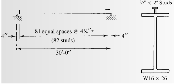
(c)
Selecting the stud anchors.
Answer to Problem 9.8.7P
We will use
Explanation of Solution
Calculation:
From AISC specifications, compute the maximum stud diameter using the equation:
Where,
Substitute the values, we get
Try for the studs of size
From table 3-21 for lightweight concrete take one stud at each of the beam position.
The number of studs for half beam can be found as follows:
Substitute the values, we have
Compute the number of studs as follows:
Substitute the value of
Calculate the spacing of the studs as follows:
Compute the minimum longitudinal spacing for studs using the equation
Where,
Substitute the values
Compute the minimum transverse spacing for studs using the equation
Where,
Substitute the values
Compute the maximum longitudinal spacing for studs using the equation
Where,
Substitute the values
But the upper limit of the spacing is 36 inches.
Calculate the require spacing for one stud at each of the section:
Substitute the values, we have
Conclusion:
Therefore, we will use
Want to see more full solutions like this?
Chapter 9 Solutions
STEEL DESIGN W/ ACCESS


- What are the total earned work hours at completion for the column forms?arrow_forward6000 units have been installed to date with 9,000 units to install. Labor costs are $23,300.00 to date. What is the unit cost for labor to date?arrow_forwardThe base rate for labor is $15/hr. The labor burden is 35% and 3% for small tools for the labor. There are 1000 units to install. Records indicate that trade workers can install 10 units per hour, per trade worker. The owners need 15% overhead and profit to pay bills, pay interest on loan and provide some profit to the partners. What is the minimum bid assuming no risk avoidance factor?arrow_forward
- 5. (20 Points) Consider a channel width change in the same 7-foot wide rectangular in Problem 4. The horizontal channel narrows as depicted below. The flow rate is 90 cfs, and the energy loss (headloss) through the transition is 0.05 feet. The water depth at the entrance to the transition is initially 4'. 1 b₁ TOTAL ENERGY LINE V² 129 У1 I b₂ TOP VIEW 2 PROFILE VIEW h₁ = 0.05 EGL Y₂ = ? a) b) c) 2 Determine the width, b₂ that will cause a choke at location 2. Determine the water depth at the downstream end of the channel transition (y₂) section if b₂ = 5 feet. Calculate the change in water level after the transition. Plot the specific energy diagram showing all key points. Provide printout in homework. d) What will occur if b₂ = = 1.5 ft.?arrow_forward4. (20 Points) A transition section has been proposed to raise the bed level a height Dz in a 7-foot wide rectangular channel. The design flow rate in the channel is 90 cfs, and the energy loss (headloss) through the transition is 0.05 feet. The water depth at the entrance to the transition section is initially 4 feet. b₁ = b = b2 1 TOTAL ENERGY LINE V² 129 Ут TOP VIEW 2 hloss = 0.05 " EGL Y₂ = ? PROFILE VIEW a) Determine the minimum bed level rise, Dz, which will choke the flow. b) If the step height, Dz = 1 ft, determine the water depth (y2) at the downstream end of the channel transition section. Calculate the amount the water level drops or rises over the step. c) Plot the specific energy diagram showing all key points. Provide printout in Bework. d) What will occur if Dz = 3.0 ft.?. Crest Front Viewarrow_forward1. (20 Points) Determine the critical depth in the trapezoidal drainage ditch shown below. The slope of the ditch is 0.0016, the side slopes are 1V:2.5H, the bottom width is b = 14', and the design discharge is 500 cfs. At this discharge the depth is y = 4.25'. Also, determine the flow regime and calculate the Froude number. Ye= ? Z barrow_forward
 Steel Design (Activate Learning with these NEW ti...Civil EngineeringISBN:9781337094740Author:Segui, William T.Publisher:Cengage Learning
 Materials Science And Engineering PropertiesCivil EngineeringISBN:9781111988609Author:Charles GilmorePublisher:Cengage Learning
 Traffic and Highway EngineeringCivil EngineeringISBN:9781305156241Author:Garber, Nicholas J.Publisher:Cengage Learning
 Architectural Drafting and Design (MindTap Course...Civil EngineeringISBN:9781285165738Author:Alan Jefferis, David A. Madsen, David P. MadsenPublisher:Cengage Learning
 Construction Materials, Methods and Techniques (M...Civil EngineeringISBN:9781305086272Author:William P. Spence, Eva KultermannPublisher:Cengage Learning
 Fundamentals Of Construction EstimatingCivil EngineeringISBN:9781337399395Author:Pratt, David J.Publisher:Cengage,