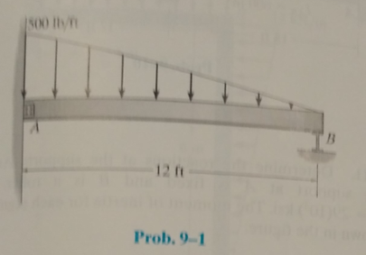
Determine the reactions at the suooorts, then draw the shear and moment diagrams. Assume the support at A is fixed and B is a roller, EI is constant.
The reactions at the supports and to draw the shear and moment diagrams.
Answer to Problem 9.1P
The vertical reaction at support A is
The horizontal reaction at support A is
The reaction moment at support A is
The vertical reaction at support B is
The shear diagram is shown below.

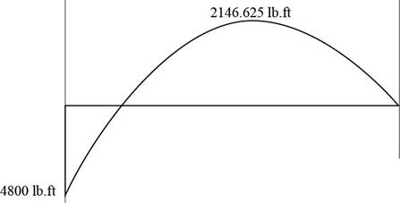
The moment diagram is shown below.
Explanation of Solution
Concept Used:
Write the expression for the net force balance in the vertical direction of the beam.
Here,
Write the expression for the net force balance in the horizontal direction in the beam.
Here,
Write the expression for the net moment about end
Here,
Calculations:
The free body diagram for the beam is shown below.
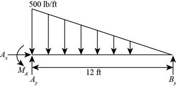
Figure (1)
Here, the vertical reaction at point
Calculate the support reactions using Equation (II).
The uniformly varying load is replaced by a concentrated force of magnitude
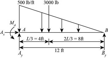
Figure (2)
Consider the moment at point A using Equation (III).
The displacement of the beam for the given load is shown below.
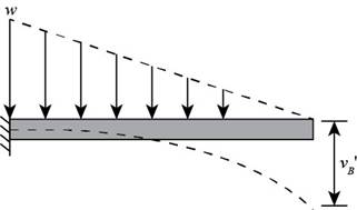
Figure (3)
Calculate the displacement of the beam for the given load.
Here, the displacement of the beam for the given load is
The displacement of the beam for the reaction at point B. is shown below.
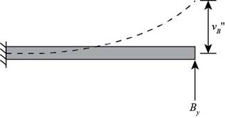
Calculate the displacement of the beam for the given load.
Here, the displacement of the beam for the reaction at point B is
Add Equation (VI) and Equation (VII) for the displacement values according to the compatibility condition.
Substitute
Calculate the vertical reaction at A using Equation (IV).
Substitute
Calculate the bending moment at A using Equation (V).
Substitute
Consider the beam as shown below.
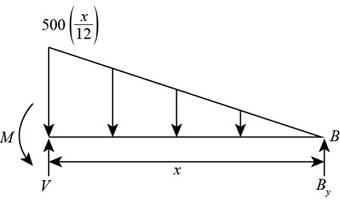
Figure (5)
Write the equation to determine the shear in the beam.
Calculate shear force at a distance
Substitute
Calculate shear force at a distance
Substitute
Calculate shear force at a distance
Substitute
Calculate shear force at a distance
Substitute
Calculate shear force at a distance
Substitute
Substitute
Write the expression for the bending moment.
Calculate moment at a distance
Substitute
Calculate moment at a distance
Substitute
Calculate moment at a distance
Substitute
Calculate moment at a distance
Substitute
Calculate moment at a distance
Substitute
Calculate moment at a distance
Substitute
Conclusion:
The vertical reaction at support A is
The horizontal reaction at support A is
The reaction moment at support A is
The vertical reaction at support B is
The shear diagram is shown below
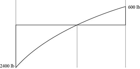
Figure (6)
The moment diagram is shown below

Figure (7)
Want to see more full solutions like this?
Chapter 9 Solutions
Structural Analysis (10th Edition)
Additional Engineering Textbook Solutions
Concepts Of Programming Languages
Starting Out with Python (4th Edition)
Introduction To Programming Using Visual Basic (11th Edition)
Thinking Like an Engineer: An Active Learning Approach (4th Edition)
Java: An Introduction to Problem Solving and Programming (8th Edition)
Modern Database Management

- 6. A lake with no outlet is fed by a river with a constant flow of 1200 ft3/s. Water evaporates from the surface at a constant rate of 13 ft3/s per square mile of surface area. The surface area varies with the depth h (in feet) as A (square miles) = 4.5 + 5.5h. What is the equilibrium depth of the lake? Below what river discharge (volume flow rate) will the lake dry up?arrow_forwardProblem 5 (A, B, C and D are fixed). Find the reactions at A and D 8 k B 15 ft A -20 ft C 10 ft Darrow_forwardProblem 4 (A, B, E, D and F are all pin connected and C is fixed) Find the reactions at A, D and F 8 m B 6m E 12 kN D F 4 marrow_forward
- Problem 1 (A, C and D are pins) Find the reactions and A, C and D. D 6 m B 12 kN/m 8 m A C 6 marrow_forwardUniform Grade of Pipe Station of Point A is 9+50.00. Elevation Point A = 250.75.Station of Point B is 13+75.00. Elevation Point B = 244.10 1) Calculate flowline of pipe elevations at every 50 ft. interval (Half Station). 2) Tabulate station and elevation for each station like shown on example 3) Draw Sketcharrow_forward40m 150N B 40marrow_forward
- Note: Please accurately answer it!. I'll give it a thumbs up or down based on the answer quality and precision. Question: What is the group name of Sample B in problem 3 from the image?. By also using the ASTM flow chart!. This unit is soil mechanics btwarrow_forwardPick the rural location of a project site in Victoria, and its catchment area-not bigger than 25 sqkm, and given the below information, determine the rainfall intensity for ARI = 5, 50, 100 year storm event. Show all the details of the procedure. Each student must propose different length of streams and elevations. Use fig below as a sample only. Pt. E-ht. 95.0 200m 600m PLD-M. 91.0 300m Pt. C-93.0 300m PL.B-ht. 92.0 PL.F-ht. 96.0 500m Pt. A-M. 91.00 To be deemed satisfactory the solution must include: Q.F1.1.Choice of catchment location Q.F1.2. A sketch displaying length of stream and elevation Q.F1.3. Catchment's IFD obtained from the Buro of Metheorology for specified ARI Q.F1.4.Calculation of the time of concentration-this must include a detailed determination of the equivalent slope. Q.F1.5.Use must be made of the Bransby-Williams method for the determination of the equivalent slope. Q.F1.6.The graphical display of the estimation of intensities for ARI 5,50, 100 must be shown.arrow_forwardQUANTITY SURVEYINGarrow_forward

 Steel Design (Activate Learning with these NEW ti...Civil EngineeringISBN:9781337094740Author:Segui, William T.Publisher:Cengage Learning
 Principles of Foundation Engineering (MindTap Cou...Civil EngineeringISBN:9781305081550Author:Braja M. DasPublisher:Cengage Learning
 Residential Construction Academy: House Wiring (M...Civil EngineeringISBN:9781285852225Author:Gregory W FletcherPublisher:Cengage Learning
 Principles of Foundation Engineering (MindTap Cou...Civil EngineeringISBN:9781337705028Author:Braja M. Das, Nagaratnam SivakuganPublisher:Cengage Learning
 Materials Science And Engineering PropertiesCivil EngineeringISBN:9781111988609Author:Charles GilmorePublisher:Cengage Learning