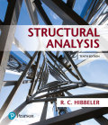
Determine the reactions at the suooorts, then draw the shear and moment diagrams. Assume the support at A is fixed and B is a roller, EI is constant.
The reactions at the supports and to draw the shear and moment diagrams.
Answer to Problem 9.1P
The vertical reaction at support A is
The horizontal reaction at support A is
The reaction moment at support A is
The vertical reaction at support B is
The shear diagram is shown below.

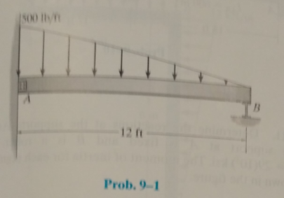
The moment diagram is shown below.
Explanation of Solution
Concept Used:
Write the expression for the net force balance in the vertical direction of the beam.
Here,
Write the expression for the net force balance in the horizontal direction in the beam.
Here,
Write the expression for the net moment about end
Here,
Calculations:
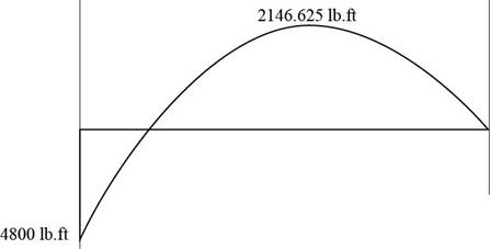
The free body diagram for the beam is shown below.
Figure (1)
Here, the vertical reaction at point
Calculate the support reactions using Equation (II).
The uniformly varying load is replaced by a concentrated force of magnitude
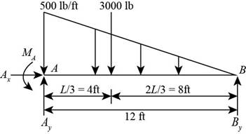
Figure (2)
Consider the moment at point A using Equation (III).
The displacement of the beam for the given load is shown below.
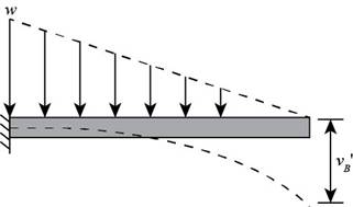
Figure (3)
Calculate the displacement of the beam for the given load.
Here, the displacement of the beam for the given load is
The displacement of the beam for the reaction at point B. is shown below.
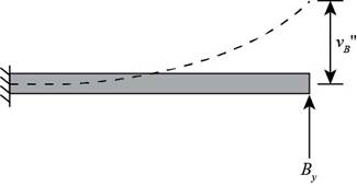
Calculate the displacement of the beam for the given load.
Here, the displacement of the beam for the reaction at point B is
Add Equation (VI) and Equation (VII) for the displacement values according to the compatibility condition.
Substitute
Calculate the vertical reaction at A using Equation (IV).
Substitute
Calculate the bending moment at A using Equation (V).
Substitute
Consider the beam as shown below.
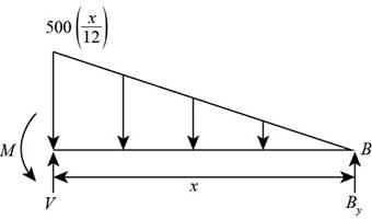
Figure (5)
Write the equation to determine the shear in the beam.
Calculate shear force at a distance
Substitute
Calculate shear force at a distance
Substitute
Calculate shear force at a distance
Substitute
Calculate shear force at a distance
Substitute
Calculate shear force at a distance
Substitute
Substitute
Write the expression for the bending moment.
Calculate moment at a distance
Substitute
Calculate moment at a distance
Substitute
Calculate moment at a distance
Substitute
Calculate moment at a distance
Substitute
Calculate moment at a distance
Substitute
Calculate moment at a distance
Substitute
Conclusion:
The vertical reaction at support A is
The horizontal reaction at support A is
The reaction moment at support A is
The vertical reaction at support B is
The shear diagram is shown below
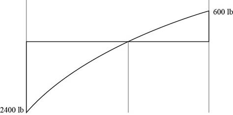
Figure (6)
The moment diagram is shown below

Figure (7)
Want to see more full solutions like this?
Chapter 9 Solutions
EBK STRUCTURAL ANALYSIS
Additional Engineering Textbook Solutions
Concepts Of Programming Languages
Starting Out with Python (4th Edition)
Introduction To Programming Using Visual Basic (11th Edition)
Thinking Like an Engineer: An Active Learning Approach (4th Edition)
Java: An Introduction to Problem Solving and Programming (8th Edition)
Modern Database Management

- 10. A short column is subjected to an eccentric loading. The axial load P = 1000 kips and the eccentricity e = 12 in. The material strengths are fy = 60 ksi and f = 6000 psi. The Young's modulus of steel is 29000 ksi. (a) Fill in the blanks in the interaction diagram shown below. (2pts each, 10pt total) Po Pn (1) failure range H 3" 30" Ast 6 No. 10 bars = P 22" I e H 3" (4) e = e small Load path for given e Radial lines show constant (2) eb (3) e large failure range Mn (5) e= Mo (b) Compute the balanced failure point, i.e., P and Mb.arrow_forwardNo chatgpt plsarrow_forward11. The prestressed T beam shown below is pretensioned using low relaxation stress-relieved Grade 270 strands. The steel area Aps = 2.5 in². The tensile strength is fpu = 270 ksi, and the concrete compressive strength is fr = 6000 psi. (a) Calculate the nominal moment strength Mn with hr = 6 in. 22" 15" T hf (b) Since this beam is a T-beam, the nominal moment strength M₁ increases with a thicker hf. However, M, stops increasing if he reaches a value. Determine the minimum thickness hy that can achieve the maximum nominal moment strength Mr. Also, calculate the corresponding maximum nominal moment strength Mn with the computed hf.arrow_forward
- 10. A short column is subjected to an eccentric loading. The axial load P = 1000 kips and the eccentricity e = 12 in. The material strengths are fy = 60 ksi and f = 6000 psi. The Young's modulus of steel is 29000 ksi. (a) Fill in the blanks in the interaction diagram shown below. 30" Ast 6 No. 10 bars = Pn (1) Po (4) e = e small Load path for given e failure range Radial lines show constant (2) eb (3) e large failure range Mn (5) e= Mo (b) Compute the balanced failure point, i.e., P and Mb. H 3" P 22" I e H 3"arrow_forward10. A short column is subjected to an eccentric loading. The axial load P = 1000 kips and the eccentricity e = 12 in. The material strengths are fy = 60 ksi and f = 6000 psi. The Young's modulus of steel is 29000 ksi. (a) Fill in the blanks in the interaction diagram shown below. 30" Ast 6 No. 10 bars = Pn (1) Po (4) e = e small Load path for given e failure range Radial lines show constant (2) eb (3) e large failure range Mn (5) e= Mo (b) Compute the balanced failure point, i.e., P and Mb. H 3" P 22" I e H 3"arrow_forward7. Match the given strand profiles with the corresponding loading conditions for a prestressed concrete (PSC) beam. Strand profile (b) (d) (c) (a) Ꮎ Load on a beamarrow_forward
- 4. For serviceability considerations, the effective moment of inertia (Ie) is calculated using the following formula: le 1 - 1cr ((2/3) Mcr) Ma 2 - وا ≥ Note that the upper bound was previously set as Iut in the earlier ACI equation. (a) Arrange the following moment of inertia values in ascending order (from smallest to largest): le, Ier, Ig and lut (b) Mer is the cracking moment. Choose the cross-section that should be used to compute Mcr. NA. h 5. Identify and circle the figure that represents the scenario in which the torsional effect is permitted to be reduced according to the ACI code provisions. (3 pts) mt mi B (b)arrow_forwardI will rate, thanksarrow_forward. 9. A reinforced concrete beam is subjected to V/ = 40 kips and Tu/ = 12 ft kips at the critical section. Given conditions: ⚫ Longitudinal reinforcements use No. 8 grade 60 steel with an effective depth d = 20 in. For shear capacity, V = 18 kips and V₂ = 22 kips • For transverse reinforcements, use No. 3 bars with grade 60. • The effective torsional area of A. = 150 in². • Crack angle = 45° ⚫ The minimum stirrup spacing is Smin = 4" and the maximum stirrup spacing is Smax = Find the required stirrup spacing at the critical section. 8".arrow_forward
- 3. The beam shown on the right uses three No. 8 bars made of Grade 60 steel as longitudinal reinforcement. The allowable maximum center-to-center spacing of the longitudinal rebars has been determined to be 10 inches. Now assume that Grade 80 steel will be used instead. Determine whether the beam satisfies the rebar spacing requirements according to the ACI Code. Additional assumptions: • Estimate fs = fy • 20" Clear cover: ? 12" Clear side cover: 1.5" The clear cover depth cc and the clear side cover remain unchanged, regardless of the change in material.arrow_forward6. For the slender columns shown below: a) Determine the effective buckling length factor (k) for each column. b) Circle the column with the largest buckling capacity, assuming all columns have the same length (f) and the same flexural rigidity (E+I) k = (a) (b) (c) (d)arrow_forward5. Identify and circle the figure that represents the scenario in which the torsional effect is permitted to be reduced according to the ACI code provisions. mi (a) V7+ B (b)arrow_forward

 Steel Design (Activate Learning with these NEW ti...Civil EngineeringISBN:9781337094740Author:Segui, William T.Publisher:Cengage Learning
 Principles of Foundation Engineering (MindTap Cou...Civil EngineeringISBN:9781305081550Author:Braja M. DasPublisher:Cengage Learning
 Residential Construction Academy: House Wiring (M...Civil EngineeringISBN:9781285852225Author:Gregory W FletcherPublisher:Cengage Learning
 Principles of Foundation Engineering (MindTap Cou...Civil EngineeringISBN:9781337705028Author:Braja M. Das, Nagaratnam SivakuganPublisher:Cengage Learning
 Materials Science And Engineering PropertiesCivil EngineeringISBN:9781111988609Author:Charles GilmorePublisher:Cengage Learning