
Videos
Find the moment and product of inertia of the area with respect to x and y axes about through
Answer to Problem 9.192RP
The moment of inertia of the area with respect to x about through
The moment of inertia of the area with respect to y about through
The product of inertia of the area with respect to x and y axes about through
Explanation of Solution
Sketch the cross section as shown in Figure 1.
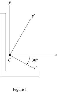
Refer to Figure 9.13.
The moment of inertia
The moment of inertia
Refer to Problem 9.191.
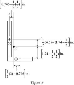
Sketch the cross section as shown in Figure 2.
Express the product of inertia as shown below:
Here,
Applying parallel axis theorem,
When the x and y axis is symmetry.
Refer to Figure 1.
Find the area of semicircle section 1 as shown below:
Here,
Substitute
Find the area of rectangle section 2 as shown below:
Here,
Substitute
Find the centroid for section 1 about x axis
Find the centroid for section 1 about x axis
Find the centroid for section 1 about y axis
Find the centroid for section 2 about x axis
Find the product of inertia of the area with respect to x and y axes by using parallel axis theorem as shown below:
Substitute
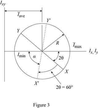
The Mohr circle is defined by the diameter XY, where
Find the average moment of inertia
Here,
Substitute
Find the radius (R) using the relation as shown below:
Here, R is radius and
Substitute
Sketch the Mohr circle as shown in Figure 3.
Refer to Figure 2.
Substitute
Find the angle
Find the moment of inertia of the area with respect to x about through
Here,
Substitute
Thus, the moment of inertia of the area with respect to x about through
Find the moment of inertia of the area with respect to y about through
Substitute
Thus, the moment of inertia of the area with respect to y about through
Find the product of inertia of the area with respect to y about through
Substitute
Thus, the product of inertia of the area with respect to x and y axes about through
(b)
Find the orientation of the principal axes through the centroid and corresponding values.
(b)
Answer to Problem 9.192RP
The orientation of the principal axes at the origin is
The maximum moment of inertia is
The minimum moment of inertia is
Explanation of Solution
Calculation:
Find the orientation of the principal axes through at origin as shown below.
Refer part a.
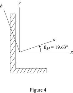
Thus, the orientation of the principal axes at the origin is
Sketch the orientation axis as shown in Figure 4.
Find the maximum moment
Substitute
Thus, the maximum moment of inertia is
Find the minimum moment
Substitute
Thus, the minimum moment of inertia is
Want to see more full solutions like this?
Chapter 9 Solutions
VECTOR MECHANICS FOR ENGINEERS: STATICS


- Solve this problem and show all of the workarrow_forwardSolve this problem and show all of the workarrow_forwardThe 4-lbs piece of putty is dropped 12 ft onto the 16-lbs block initially at rest on the two springs, each with a stiffness k = 5 lbs/in. Calculate the additional deflection d of the springs due to the impact of the putty, which adheres to the block upon contact.arrow_forward
- Solve this probem. Draw the diagram and show how the moments are calculated in all of the directionsarrow_forwardSolve this problem and show all of the workarrow_forwardThe 4-lbs piece of putty is dropped 12 ft onto the 16-lbs block initially at rest on the two springs, each with a stiffness k = 5 lbs/in. Calculate the additional deflection d of the springs due to the impact of the putty, which adheres to the block upon contact.arrow_forward
- A converging elbow (see the figure below) turns water through an angle of 135° in a vertical plane. The flow cross section diameter is 400 mm at the elbow inlet, section (1), and 200 mm at the elbow outlet, section (2). The elbow flow passage volume is 0.2 m³ between sections (1) and (2). The water volume flowrate is 0.1 m³/s and the elbow inlet and outlet pressures are 140 kPa and 90 kPa. The elbow mass is 11 kg. Calculate the (a) horizontal (x direction) and (b) vertical (z direction) anchoring forces required to hold the elbow in place. D₂- Section (1)- D₁ = 400 mm 135° 200 mm Section (2) (a) Fx= i 20809.96 N (b) Fz= i -120265 Narrow_forward2: A rectangular aluminum block is loaded uniformly in three directions. The loadings are as follows:a 50 kN total resulting compressive load in the x-direction, a 200 kPa uniformly distributed tensile load in they-direction, and a 0.03 MN total resulting tensile load in the z-direction. The block has the following dimensions:L = 1 m, b = 20 cm, h = 350 mm. Use E = 70 GPa and ν = 0.25.Determine the strain in the x and y axes respectively. For the strain in the y-direction to be equal to 0, how much uniformly distributed load inthe surface of y-direction should be added? (+ for tensile, - for compressive) Answers: 5 -1.122 x10⁻⁵ / 3 decimals 6 5.102 x10⁻⁶ / 3 decimals 7 -0.357 MPa / 3 decimalsarrow_forwardA spherical balloon with a diameter of 9 m is filled with water vapour at 200˚C and 200 kPa. Determine the mass of water in the balloon. The R value for water is 0.4615 kJ/kg∙K.arrow_forward
- Correct answers are written below. Detailed and correct solution only with fbd. I will upvote. 1: A 3 m alloy shaft fixed at one end has a torsional shearing stress capacity of 55 MPa. Due to improper fabrication, its cross-sectionalarea has become irregularly shaped. Its effective polar moment of inertia has become 2 x10⁻⁷ m4, and the maximum torque stress acts at 7.5 cm fromthe center of the shaft.[1]: If the shaft is to be replaced by a properly manufactured solid circular shaft that has a maximumshearing stress capacity of 70 MN/m2, what is the minimum diameter required so it can withstand the sameload? [2]: Calculate the thickness of a hollow circular shaft with the same outside diameter calculated initem [1] that can carry the same load. Limit the maximum shearing stress of the hollow circular shaft to0.09 GPa.Determine the angle of twist on the free end of the shaft. Use G = 150 x103 GPa. [3]: Use the solidcircular shaft from [1] and use the hollow circular shaft from [2].…arrow_forwardtwo closed 1 m3 chambers are filled with fluid at 25˚C and 1 atm. One is filled with pure carbon dioxide and one is filled with pure water. Only considering the weight of the fluids, which chamber is heavier?arrow_forwardCorrect answers are written below. Detailed and correct solution only with fbd. I will upvote. 1: A 3 m alloy shaft fixed at one end has a torsional shearing stress capacity of 55 MPa. Due to improper fabrication, its cross-sectionalarea has become irregularly shaped. Its effective polar moment of inertia has become 2 x10⁻⁷ m4, and the maximum torque stress acts at 7.5 cm fromthe center of the shaft.[1]: If the shaft is to be replaced by a properly manufactured solid circular shaft that has a maximumshearing stress capacity of 70 MN/m2, what is the minimum diameter required so it can withstand the sameload? [2]: Calculate the thickness of a hollow circular shaft with the same outside diameter calculated initem [1] that can carry the same load. Limit the maximum shearing stress of the hollow circular shaft to0.09 GPa.Determine the angle of twist on the free end of the shaft. Use G = 150 x103 GPa. [3]: Use the solidcircular shaft from [1] and use the hollow circular shaft from [2].…arrow_forward
 Elements Of ElectromagneticsMechanical EngineeringISBN:9780190698614Author:Sadiku, Matthew N. O.Publisher:Oxford University Press
 Mechanics of Materials (10th Edition)Mechanical EngineeringISBN:9780134319650Author:Russell C. HibbelerPublisher:PEARSON
 Thermodynamics: An Engineering ApproachMechanical EngineeringISBN:9781259822674Author:Yunus A. Cengel Dr., Michael A. BolesPublisher:McGraw-Hill Education
 Control Systems EngineeringMechanical EngineeringISBN:9781118170519Author:Norman S. NisePublisher:WILEY
 Mechanics of Materials (MindTap Course List)Mechanical EngineeringISBN:9781337093347Author:Barry J. Goodno, James M. GerePublisher:Cengage Learning
 Engineering Mechanics: StaticsMechanical EngineeringISBN:9781118807330Author:James L. Meriam, L. G. Kraige, J. N. BoltonPublisher:WILEY