The three air carts shown in Figure 9-44 have masses, reading from left to right, of m , 2 m , and 4 m , respectively Initially the cart on the right is at rest, whereas the other two carts are moving to the right with a speed u 0 . All carts are equipped with putty bumpers that give completely inelastic collisions. (a) Find the final speed of the carts. (b) Calculate the ratio of the final kinetic energy of the system to the initial kinetic energy. Figure 9-44 Problem 81
The three air carts shown in Figure 9-44 have masses, reading from left to right, of m , 2 m , and 4 m , respectively Initially the cart on the right is at rest, whereas the other two carts are moving to the right with a speed u 0 . All carts are equipped with putty bumpers that give completely inelastic collisions. (a) Find the final speed of the carts. (b) Calculate the ratio of the final kinetic energy of the system to the initial kinetic energy. Figure 9-44 Problem 81
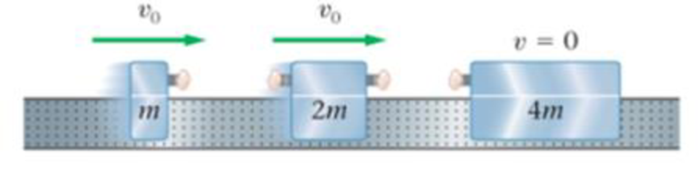
The three air carts shown in Figure 9-44 have masses, reading from left to right, of m, 2m, and 4m, respectively Initially the cart on the right is at rest, whereas the other two carts are moving to the right with a speed u0. All carts are equipped with putty bumpers that give completely inelastic collisions. (a) Find the final speed of the carts. (b) Calculate the ratio of the final kinetic energy of the system to the initial kinetic energy.
A 0.850-m-long metal bar is pulled to the right at a steady 5.0 m/s perpendicular to a uniform, 0.650-T magnetic field. The bar rides on parallel metal rails connected through a 25-Ω, resistor (Figure 1), so the apparatus makes a complete circuit. Ignore the resistance of the bar and the rails. Please explain how to find the direction of the induced current.
For each of the actions depicted, determine the direction (right, left, or zero) of the current induced to flow through the resistor in the circuit containing the secondary coil. The coils are wrapped around a plastic core. Immediately after the switch is closed, as shown in the figure, (Figure 1) in which direction does the current flow through the resistor? If the switch is then opened, as shown in the figure, in which direction does the current flow through the resistor? I have the answers to the question, but would like to understand the logic behind the answers. Please show steps.
When violet light of wavelength 415 nm falls on a single slit, it creates a central diffraction peak that is 8.60
cm wide on a screen that is 2.80 m away.
Part A
How wide is the slit?
ΟΙ ΑΣΦ
?
D= 2.7.10-8
Submit Previous Answers Request Answer
× Incorrect; Try Again; 8 attempts remaining
m
Applications and Investigations in Earth Science (9th Edition)
Knowledge Booster
Learn more about
Need a deep-dive on the concept behind this application? Look no further. Learn more about this topic, physics and related others by exploring similar questions and additional content below.


 Physics for Scientists and Engineers: Foundations...PhysicsISBN:9781133939146Author:Katz, Debora M.Publisher:Cengage Learning
 Principles of Physics: A Calculus-Based TextPhysicsISBN:9781133104261Author:Raymond A. Serway, John W. JewettPublisher:Cengage Learning
 University Physics Volume 1PhysicsISBN:9781938168277Author:William Moebs, Samuel J. Ling, Jeff SannyPublisher:OpenStax - Rice University
 College PhysicsPhysicsISBN:9781285737027Author:Raymond A. Serway, Chris VuillePublisher:Cengage Learning
 Physics for Scientists and Engineers, Technology ...PhysicsISBN:9781305116399Author:Raymond A. Serway, John W. JewettPublisher:Cengage Learning
 Physics for Scientists and Engineers with Modern ...PhysicsISBN:9781337553292Author:Raymond A. Serway, John W. JewettPublisher:Cengage Learning