
Find the maximum negative bending moment at point B.
Answer to Problem 1P
The maximum negative bending moment at point B is
Explanation of Solution
Given Information:
The concentrated live load (P) is 75 kN.
Calculation:
Apply a 1 kN unit moving load at a distance of x from left end A.
Sketch the free body diagram of beam as shown in Figure 1.
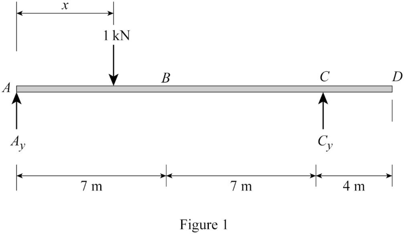
Refer Figure 1.
Find the equation of support reaction
Take moment about point A.
Consider moment equilibrium at point A.
Consider clockwise moment as positive and anticlockwise moment as negative.
Sum of moment at point A is zero.
Find the equation of support reaction
Apply vertical equilibrium equation of forces.
Consider upward force as positive
Substitute
Find the equation of moment at B.
Apply 1 kN at just left of B
Sketch the free body diagram of the section AB as shown in Figure 2.
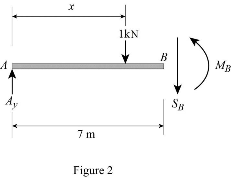
Refer Figure 2.
Consider moment at B.
Consider clockwise moment as positive and anticlockwise moment as negative.
Substitute
Apply 1 kN at just right of B
Sketch the free body diagram of the section BD as shown in Figure 3.
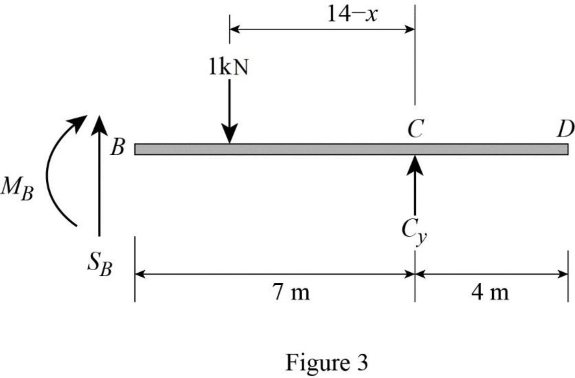
Refer Figure 3.
Consider moment at B.
Consider clockwise moment as positive and anticlockwise moment as negative.
Find the equation of moment at B of portion BC
Substitute
Thus, the equations of the influence line for
Find the value of influence line ordinate of moment at various points of x using the Equations (3) and (4) and summarize the value as in Table 1.
| x | |
| 0 | 0 |
| 7 | |
| 14 | 0 |
| 28 | –2 |
Draw the influence lines for the moment at point B using Table 4 as shown in Figure 4.
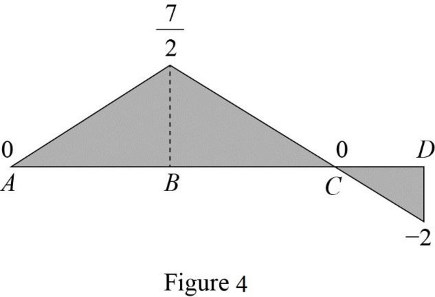
Refer Figure 4,
The maximum negative influence line ordinate of bending moment at B is
Find the maximum negative bending moment at point B using the equation.
Substitute 75 kN for P and
Therefore, the maximum negative bending moment at point B is
Want to see more full solutions like this?
Chapter 9 Solutions
EBK STRUCTURAL ANALYSIS

- I want an answer very quickly, pleasearrow_forwardQ1/ Choose the correct answer for the following: 1- Cantilever retaining walls is suitable for retaining backfill about a- 8m d-4m b- 12m c- 2m e- Any height 2-The shear key is provided to a- Avoid friction behind the wall d- All of the above b- Improve appearance e- None of the above c- Increase passive resistance types of retaining wall may b- Semi-gravity retaining walls d-Counterfort retaining walls be classified as follows: 3- The common a- Gravity retaining walls walls c- Cantilever retaining e- All the mentioned 4-Related to Stability of RW, Which of the following does not represent a potential failure mode for a retaining wall? a-Bearing capacity failure of the foundation soil. b- Wall cracking due to thermal expansion. c- Excessive settlement due to weak soil layer. d- Shear failure within the foundation soil adjacent to the wall. e-Sliding along the base due to insufficient friction. 5- If the desired factor of safety against sliding is not met, which strategy is NOT a…arrow_forwardI want an answer very quickly, pleasearrow_forward
- I need a solution quickly, pleasearrow_forwardI need a solution quickly, pleasearrow_forwardFor the truss shown in Fig 2, determine the nodal displacement and member forces using the stifness method for all elements of the truss. Assume for each member A = 0.0015 m2 and E = 200 GPa please show all workingarrow_forward
- Two W14x38 tension members are connected with a splice connection using plates attached atthe top and the bottom flanges. The design axial load Pu is 320 kips. The bolts are made of A325X, and thebolt diameter is ½ inch. (Slip-Critical connection)( LRFD units)( Previous Solution was incomplete/incorrect)arrow_forwardA tension member made of L4x4x1/2 is connected to gusset plate with welds. Using E70electrode and ½ inch weld size, design the balanced weld lengths.( Use AISC manual, LRFD units)(Previous solution was incorrect)arrow_forwardTwo W14x38 tension members are connected with a splice connection using plates attached atthe top and the bottom flanges. The design axial load Pu is 320 kips. The bolts are made of A325X, and thebolt diameter is ½ inch. (Slip-Critical connection)( LRFD units)arrow_forward
- A tension member made of L4x4x1/2 is connected to gusset plate with welds. Using E70electrode and ½ inch weld size, design the balanced weld lengths.( Use AISC manual, LRFD units)arrow_forward= A steel pile (H-section; HP 310 x 125; and so A, 15.9 x 10⁻³ m² ) is driven into a layer of sandstone. The length of the pile is 25 m. Following are the properties of the sandstone: unconfined compression strength = qu(lab) = 78 MN/m² and angle of friction = 36°. Using a factor of safety of 3, estimate the allowable point load that can be carried by the pile. Use [qu(d Qu(lab). qu(design) b)/5]. (Enter your answer to three significant figures.) Qp(all) kNarrow_forwardСи A concrete pile 20 m long having a cross section of 0.25 m x 0.25 m is fully embedded in a saturated clay layer. For the clay, given: Ysat = 18 kN/m³, = 0, and c₁ = 80 kN/m². Determine the allowable load that the pile can carry (FS-3). Use the A method to estimate the skin resistance. For L = 20 m, A = 0.173. (Enter your answer to three significant figures.) Qall kNarrow_forward
