
Videos
Compare the thermal efficiency of the cycle when it is operated such that the saturated liquid enters the pump against that when the sub-cooled liquid enters the pump.
Explanation of Solution
Given:
Pressure of steam at the boiler
Pressure of steam at the condenser
Temperature of steam at the turbine inlet
Temperature of sub-cooled liquid
Calculation:
Draw the
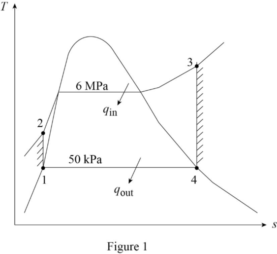
The pressures are constant for the process 2 to 3 and process 4 to 1.
The entropies are constant for the process 1 to 2 and process 3 to 4.
The thermal efficiency of the cycle when it is operated such that when the saturated liquid enters the pump:
Refer Table A-5, “Saturated water-Pressure table”, obtain the specific enthalpy and specific volume at state 1 corresponding to the pressure of
Calculate the work done by the pump during process 1-2
Calculate the specific enthalpy at state 2
Refer Table A-6, “Superheated water”, obtain the specific enthalpy and temperature at state 3 corresponding to the pressure of
Refer Table A-5, “Saturated water-Pressure table”, obtain the following properties corresponding to the pressure of
Calculate the quality of steam at state 4
Calculate the specific enthalpy at state 4
Calculate the thermal efficiency of the cycle
The thermal efficiency of the cycle when it is operated such that when the sub-cooled liquid enters the pump:
Refer Table A-5, “Saturated water-Pressure table”, obtain the saturation temperature corresponding to the pressure of
Calculate the temperature at state 1
Refer Table A-4, “Saturated water-Temperature table”, obtain the specific enthalpy and specific volume at state 1 corresponding to the temperature of
Calculate the work done by the pump during process 1-2
Calculate the enthalpy at state 2
Calculate the thermal efficiency of the cycle
By comparing the thermal efficiencies of the cycle, it is found that the thermal efficiency slightly reduces because of the sub-cooling at the inlet of the pump.
Want to see more full solutions like this?
Chapter 9 Solutions
EBK FUNDAMENTALS OF THERMAL-FLUID SCIEN


- Uppgift 2 (9p) I77777 20 kN 10 kN/m 4 [m] 2 2 Bestäm tvärkrafts- och momentdiagram för balken i figuren ovan. Extrempunkter ska anges med både läge och värde i diagrammen.arrow_forward**Problem 8-45.** The man has a mass of 60 kg and the crate has a mass of 100 kg. If the coefficient of static friction between his shoes and the ground is \( \mu_s = 0.4 \) and between the crate and the ground is \( \mu_c = 0.3 \), determine if the man is able to move the crate using the rope-and-pulley system shown. **Diagram Explanation:** The diagram illustrates a scenario where a man is attempting to pull a crate using a rope-and-pulley system. The setup is as follows: - **Crate (C):** Positioned on the ground with a rope attached. - **Rope:** Connects the crate to a pulley system and extends to the man. - **Pulley on Tree:** The rope runs over a pulley mounted on a tree which redirects the rope. - **Angles:** - The rope between the crate and tree forms a \(30^\circ\) angle with the horizontal. - The rope between the tree and the man makes a \(45^\circ\) angle with the horizontal. - **Man (A):** Pulling on the rope with the intention of moving the crate. This arrangement tests the…arrow_forwardplease solve this problems follow what the question are asking to do please show me step by steparrow_forward
- please help me to solve this problem and determine the stress for each point i like to be explained step by step with the correct answerarrow_forwardplease solve this problem for me the best way that you can explained to solve please show me the step how to solvearrow_forwardplese solbe this problem and give the correct answer solve step by step find the forces and line actionarrow_forward
- please help me to solve this problems first write the line of action and them find the forces {fx=0: fy=0: mz=0: and them draw the shear and bending moment diagram. please explain step by steparrow_forwardplease solve this problem step by step like human and give correct answer step by steparrow_forwardPROBLEM 11: Determine the force, P, that must be exerted on the handles of the bolt cutter. (A) 7.5 N (B) 30.0 N (C) 52.5 N (D) 300 N (E) 325 N .B X 3 cm E 40 cm cm F = 1000 N 10 cm 3 cm boltarrow_forward
 Elements Of ElectromagneticsMechanical EngineeringISBN:9780190698614Author:Sadiku, Matthew N. O.Publisher:Oxford University Press
 Mechanics of Materials (10th Edition)Mechanical EngineeringISBN:9780134319650Author:Russell C. HibbelerPublisher:PEARSON
 Thermodynamics: An Engineering ApproachMechanical EngineeringISBN:9781259822674Author:Yunus A. Cengel Dr., Michael A. BolesPublisher:McGraw-Hill Education
 Control Systems EngineeringMechanical EngineeringISBN:9781118170519Author:Norman S. NisePublisher:WILEY
 Mechanics of Materials (MindTap Course List)Mechanical EngineeringISBN:9781337093347Author:Barry J. Goodno, James M. GerePublisher:Cengage Learning
 Engineering Mechanics: StaticsMechanical EngineeringISBN:9781118807330Author:James L. Meriam, L. G. Kraige, J. N. BoltonPublisher:WILEY