
Videos
a)
The rate of exergy destroyed during the process and the exit temperature
a)
Answer to Problem 66P
The rate of exergy destroyed during the process is
The exit temperature
Explanation of Solution
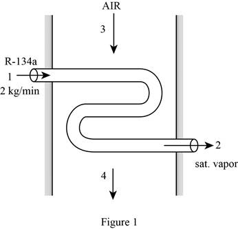
Draw the schematic diagram of the flow of refrigerant-134a through evaporator section as shown in Figure (1).
Write the expression for the mass balances equation for the heat exchanger.
Here, mass flow rate of refrigerant at inlet is
Since net mass flow rate of refrigerant-134a and air through system is 0.
From Figure (1), the mass flow rate of refrigerant-134a at
Here, initial and final mass flow rate of refrigerant at
From Figure (1), the mass flow rate of air at
Here, mass flow rate of air at
Write the expression for the enthalpy at state 1
Write the expression for the entropy at state 1
Write the expression for the mass flow rate of air
Here, gas constant of air is
Write the expression for energy balance for the heat exchanger
Here, rate of net energy transfer in to the control volume is
Substitute 0 for
Here, mass flow rate at
Write the expression for the entropy balance for the steady flow system as;
Here, rate of entropy generation is
At steady state, rate of change in entropy of the system is zero.
Substitute 0 for
Here, entropy at
Write the expression for the change between state 4 entropy
Here, temperature at state
Write the expression for the exergy destroyed rate during the process
Here, dead state temperature is
Conclusion:
Refer to Table A-12, “Saturated refrigerant-134a-Pressure table”, obtain the following properties at the pressure
Here, enthalpy of saturated liquid is
Substitute
Substitute
Refer to Table A-12, “Saturated refrigerant-134a-Pressure table”, obtain the following properties at the pressure
Here, enthalpy at state 2 is
From the Table A-2, “Ideal-gas specific heats of various common gases table”, select the gas constant of air gas
Substitute
At steady state, rate of change in internal energy of the system is zero.
From the Table A-2, “Ideal-gas specific heats of various common gases table”, select the constant pressure specific heat
Substitute
Thus, the exit temperature
Substitute
Substitute
Substitute
Thus, the rate of exergy destroyed during the process is
b)
The exit temperature of the air and the rate of exergy destroyed during the process without insulation.
b)
Answer to Problem 66P
The exit temperature of the air without insulation is
The rate of exergy destroyed during the process without insulation is
Explanation of Solution
Write the expression for the state 4 temperature
Here, heat gain is from the surrounding
Write the expression for the entropy balance For an extended system as;
Conclusion:
Substitute
Thus, the exit temperature of the air is
substitute
Substitute
Substitute
Thus, the rate of exergy destroyed during the process is
Want to see more full solutions like this?
Chapter 8 Solutions
EBK THERMODYNAMICS: AN ENGINEERING APPR


- Uppgift 2 (9p) I77777 20 kN 10 kN/m 4 [m] 2 2 Bestäm tvärkrafts- och momentdiagram för balken i figuren ovan. Extrempunkter ska anges med både läge och värde i diagrammen.arrow_forward**Problem 8-45.** The man has a mass of 60 kg and the crate has a mass of 100 kg. If the coefficient of static friction between his shoes and the ground is \( \mu_s = 0.4 \) and between the crate and the ground is \( \mu_c = 0.3 \), determine if the man is able to move the crate using the rope-and-pulley system shown. **Diagram Explanation:** The diagram illustrates a scenario where a man is attempting to pull a crate using a rope-and-pulley system. The setup is as follows: - **Crate (C):** Positioned on the ground with a rope attached. - **Rope:** Connects the crate to a pulley system and extends to the man. - **Pulley on Tree:** The rope runs over a pulley mounted on a tree which redirects the rope. - **Angles:** - The rope between the crate and tree forms a \(30^\circ\) angle with the horizontal. - The rope between the tree and the man makes a \(45^\circ\) angle with the horizontal. - **Man (A):** Pulling on the rope with the intention of moving the crate. This arrangement tests the…arrow_forwardplease solve this problems follow what the question are asking to do please show me step by steparrow_forward
- please help me to solve this problem and determine the stress for each point i like to be explained step by step with the correct answerarrow_forwardplease solve this problem for me the best way that you can explained to solve please show me the step how to solvearrow_forwardplese solbe this problem and give the correct answer solve step by step find the forces and line actionarrow_forward
- please help me to solve this problems first write the line of action and them find the forces {fx=0: fy=0: mz=0: and them draw the shear and bending moment diagram. please explain step by steparrow_forwardplease solve this problem step by step like human and give correct answer step by steparrow_forwardPROBLEM 11: Determine the force, P, that must be exerted on the handles of the bolt cutter. (A) 7.5 N (B) 30.0 N (C) 52.5 N (D) 300 N (E) 325 N .B X 3 cm E 40 cm cm F = 1000 N 10 cm 3 cm boltarrow_forward
 Elements Of ElectromagneticsMechanical EngineeringISBN:9780190698614Author:Sadiku, Matthew N. O.Publisher:Oxford University Press
 Mechanics of Materials (10th Edition)Mechanical EngineeringISBN:9780134319650Author:Russell C. HibbelerPublisher:PEARSON
 Thermodynamics: An Engineering ApproachMechanical EngineeringISBN:9781259822674Author:Yunus A. Cengel Dr., Michael A. BolesPublisher:McGraw-Hill Education
 Control Systems EngineeringMechanical EngineeringISBN:9781118170519Author:Norman S. NisePublisher:WILEY
 Mechanics of Materials (MindTap Course List)Mechanical EngineeringISBN:9781337093347Author:Barry J. Goodno, James M. GerePublisher:Cengage Learning
 Engineering Mechanics: StaticsMechanical EngineeringISBN:9781118807330Author:James L. Meriam, L. G. Kraige, J. N. BoltonPublisher:WILEY