
Statics and Mechanics of Materials Plus Mastering Engineering with Pearson eText - Access Card Package (5th Edition)
5th Edition
ISBN: 9780134301006
Author: Russell C. Hibbeler
Publisher: PEARSON
expand_more
expand_more
format_list_bulleted
Concept explainers
Videos
Textbook Question
Chapter 8.4, Problem 10P
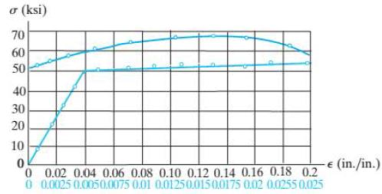
The stress–strain diagram for an aluminum alloy specimen having an original diameter of 0.5 in. and a gage length of 2 in, is given in the figure. Determine approximately the modulus of elasticity for the material, the load on the specimen that causes yielding, and the ultimate load the specimen will support.
Probs. 8–10/11/12
Expert Solution & Answer
Want to see the full answer?
Check out a sample textbook solution
Students have asked these similar questions
Consider a double-fluid manometer attached to an air pipe shown below. If the specific gravity ofone fluid is 13.8, determine the specific gravity of the other fluid for the indicated absolutepressure of air. Take the atmospheric pressure to be 95 kPa
A race car enters the circular portion of a track that has a radius of 65 m. Disregard the 70 m in the picture. When the car enters the curve at point P, it is traveling with a speed of 120 km/h that is increasing at 5 m/s^2 . Three seconds later, determine the x and y components of velocity and acceleration of the car. I'm having trouble getting the correct y component of acceleration. all the other answers are correct. thank you!
Figure: 06_P041
Copyright 2013 Pearson Education, publishing a Prentice Hall
2. Determine the force that the jaws J of the metal cutters exert on the smooth cable C if 100-N
forces are applied to the handles. The jaws are pinned at E and A, and D and B. There is also
a pin at F.
400 mm
15°
20 mm
A
15°
15
D
B
30 mm² 80 mm
20 mm
400 mm
Figure: 06_P090
Copyright 2013 Pearson Education, publishing as Prentice Hall
15°
100 N
100 N
15°
Chapter 8 Solutions
Statics and Mechanics of Materials Plus Mastering Engineering with Pearson eText - Access Card Package (5th Edition)
Ch. 8.4 - Define a homogeneous material.Ch. 8.4 - Prob. 2FPCh. 8.4 - Prob. 3FPCh. 8.4 - Prob. 4FPCh. 8.4 - Prob. 5FPCh. 8.4 - As the temperature increases the modulus of...Ch. 8.4 - Prob. 7FPCh. 8.4 - Prob. 8FPCh. 8.4 - Prob. 9FPCh. 8.4 - Prob. 10FP
Ch. 8.4 - The material for the 50-mm-long specimen has the...Ch. 8.4 - If the elongation of wire BC is 0.2 mm after the...Ch. 8.4 - A tension test was performed on a steel specimen...Ch. 8.4 - Data taken from a stressstrain test for a ceramic...Ch. 8.4 - Data taken from a stressstrain test for a ceramic...Ch. 8.4 - Prob. 4PCh. 8.4 - The stress-strain diagram for a steel alloy having...Ch. 8.4 - Prob. 6PCh. 8.4 - The rigid beam is supported by a pin at C and an...Ch. 8.4 - The rigid beam is supported by a pin at C and an...Ch. 8.4 - Prob. 9PCh. 8.4 - The stressstrain diagram for an aluminum alloy...Ch. 8.4 - The stressstrain diagram for an aluminum alloy...Ch. 8.4 - Prob. 12PCh. 8.4 - A bar having a length of 5 in. and cross-sectional...Ch. 8.4 - The rigid pipe is supported by a pin at A and an...Ch. 8.4 - The rigid pipe is supported by a pin at A and an...Ch. 8.4 - Prob. 16PCh. 8.4 - The rigid beam is supported by a pin at C and an...Ch. 8.4 - Prob. 18PCh. 8.4 - Prob. 19PCh. 8.6 - A 100 mm long rod has a diameter of 15 mm. If an...Ch. 8.6 - A solid circular rod that is 600 mm long and 20 mm...Ch. 8.6 - Prob. 15FPCh. 8.6 - Prob. 16FPCh. 8.6 - The acrylic plastic rod is 200 mm long and 15 mm...Ch. 8.6 - The plug has a diameter of 30 mm and fits within a...Ch. 8.6 - The elastic portion of the stress-strain diagram...Ch. 8.6 - The elastic portion of the stress-strain diagram...Ch. 8.6 - The brake pads for a bicycle tire arc made of...Ch. 8.6 - The lap joint is connected together using a 1.25...Ch. 8.6 - The lap joint is connected together using a 1.25...Ch. 8.6 - Prob. 27PCh. 8.6 - The shear stress-strain diagram for an alloy is...Ch. 8.6 - Prob. 29PCh. 8 - The elastic portion of the tension stress-strain...Ch. 8 - Prob. 2RPCh. 8 - Prob. 3RPCh. 8 - Prob. 4RPCh. 8 - Prob. 5RPCh. 8 - Prob. 6RPCh. 8 - The stress-strain diagram for polyethylene, which...Ch. 8 - The pipe with two rigid caps attached to its ends...Ch. 8 - Prob. 9RPCh. 8 - Prob. 10RP
Knowledge Booster


Learn more about
Need a deep-dive on the concept behind this application? Look no further. Learn more about this topic, mechanical-engineering and related others by exploring similar questions and additional content below.Similar questions
- A telemetry system is used to quantify kinematic values of a ski jumper immediately before the jumper leaves the ramp. According to the system r=560 ft , r˙=−105 ft/s , r¨=−10 ft/s2 , θ=25° , θ˙=0.07 rad/s , θ¨=0.06 rad/s2 Determine the velocity of the skier immediately before leaving the jump. The velocity of the skier immediately before leaving the jump along with its direction is ? I have 112.08 ft/s but can't seem to get the direction correct. Determine the acceleration of the skier at this instant. At this instant, the acceleration of the skier along with its direction is ? acceleration is 22.8 ft/s^2 but need help with direction. Need help with velocity direction and acceleration direction please.arrow_forwardFor Problems 18-22 (Table 7-27), design a V-belt drive. Specify the belt size, the sheave sizes, the number of belts, the actual output speed, and the center distance.arrow_forwardonly 21arrow_forward
- only 41arrow_forwardNormal and tangential components-relate to x-y coordinates A race car enters the circular portion of a track that has a radius of 65 m. When the car enters the curve at point P, it is traveling with a speed of 120 km/h that is increasing at 5 m/s^2 . Three seconds later, determine the x and y components of velocity and acceleration of the car. I need help with finding the y component of the total acceleration. I had put -32 but its incorrect. but i keep getting figures around that numberarrow_forwardThe bracket BCD is hinged at C and attached to a control cable at B. Let F₁ = 275 N and F2 = 275 N. F1 B a=0.18 m C A 0.4 m -0.4 m- 0.24 m Determine the reaction at C. The reaction at C N Z F2 Darrow_forward
- Consider the angle bar shown in the given figure A W 240 mm B 80 mm Draw the free-body diagram needed to determine the reactions at A and B when a = 150 mm. This problem could also be approached as a 3-force body using method of Section 4.2B.arrow_forwardA telemetry system is used to quantify kinematic values of a ski jumper immediately before the jumper leaves the ramp. According to the system r=560 ft , r˙=−105 ft/s , r¨=−10 ft/s2 , θ=25° , θ˙=0.07 rad/s , θ¨=0.06 rad/s2 Determine the velocity of the skier immediately before leaving the jump. The velocity of the skier immediately before leaving the jump along with its direction is ? I have 112.08 ft/s but can't seem to get the direction correct. Determine the acceleration of the skier at this instant. At this instant, the acceleration of the skier along with its direction is ? acceleration is 22.8 ft/s^2 but need help with direction. Need help with velocity direction and acceleration direction please.arrow_forwardFor the stop bracket shown, locate the x coordinate of the center of gravity. Consider a = = 16.50 mm. 34 mm 62 mm 51 mm 10 mm 100 mm 88 mm 55 mm 45 mm The x coordinate of the center of gravity is mm.arrow_forward
- In the given figure, the bent rod ABEF is supported by bearings at C and D and by wire AH. The portion AB of the rod is 250 mm long, and the load W is 580 N. Assume that the bearing at D does not exert any axial thrust. H B A с 30° 250 mm D Z 50 mm 300 mm F 250 mm 50 mm W Draw the free-body diagram needed to determine the tension in wire AH and the reactions at C and D.arrow_forwardA 10-ft boom is acted upon by the 810-lb force as shown in the figure. D 6 ft 6 ft E B 7 ft C 6 ft x 4 ft W Draw the free-body diagram needed to determine the tension in each cable and the reaction at the ball-and-socket joint at A.arrow_forwardLocate the center of gravity of the sheet-metal form shown. Given: r = 26.40 mm . 50 mm 40 mm X 150 mm The center of gravity (✗) of the sheet-metal form is The center of gravity (Y) of the sheet-metal form is The center of gravity ( Z ) of the sheet-metal form is mm. mm. (Round the final answer to three decimal places.) mm.arrow_forward
arrow_back_ios
SEE MORE QUESTIONS
arrow_forward_ios
Recommended textbooks for you
 Mechanics of Materials (MindTap Course List)Mechanical EngineeringISBN:9781337093347Author:Barry J. Goodno, James M. GerePublisher:Cengage Learning
Mechanics of Materials (MindTap Course List)
Mechanical Engineering
ISBN:9781337093347
Author:Barry J. Goodno, James M. Gere
Publisher:Cengage Learning
Material Properties 101; Author: Real Engineering;https://www.youtube.com/watch?v=BHZALtqAjeM;License: Standard YouTube License, CC-BY