
VECTOR MECHANICS FOR ENGINEERS: STATICS
12th Edition
ISBN: 9781260536225
Author: BEER
Publisher: MCG
expand_more
expand_more
format_list_bulleted
Videos
Textbook Question
Chapter 8.3, Problem 8.83P
The block and tackle shown are used to raise a 150-lb load. Each of the 3-in.-diameter pulleys rotates on a 0.5-in.-diameter axle. Knowing that the coefficient of static friction is 0.20, determine the tension in each portion of the rope as the load is slowly raised.
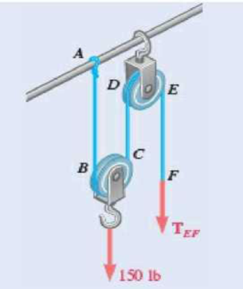
Fig. P8.83 and P8.84
Expert Solution & Answer
Want to see the full answer?
Check out a sample textbook solution
Students have asked these similar questions
The gears shown in the figure have a diametral pitch of 2 teeth per inch and a 20° pressure angle.
The pinion rotates at 1800 rev/min clockwise and transmits 200 hp through the idler pair to gear
5 on shaft c. What forces do gears 3 and 4 transmit to the idler shaft?
TS
I
y
18T
32T
This
a
12
x
18T
C
48T
5
Question 1. Draw 3 teeth for the following pinion and gear respectively. The teeth
should be drawn near the pressure line so that the teeth from the pinion should
mesh those of the gear. Drawing scale (1:1). Either a precise hand drawing or
CAD drawing is acceptable. Draw all the trajectories of the involute lines and the
circles.
Specification: 18tooth pinion and 30tooth gear. Diameter pitch=P=6 teeth /inch.
Pressure angle:20°, 1/P for addendum (a) and 1.25/P for dedendum (b). For fillet,
c=b-a.
5. The figure shows a gear train. There is no friction at the bearings except for the gear tooth forces.
The material of the milled gears is steel having a Brinell hardness of 170. The input shaft speed (n2)
is 800 rpm. The face width and the contact angle for all gears are 1 in and 20° respectively. In this
gear set, the endurance limit (Se) is 15 kpsi and nd (design factor) is 2.
(a) Find the revolution speed of gear 5.
(b) Determine whether each gear satisfies the design factor of 2.0 for bending fatigue.
(c) Determine whether each gear satisfies the design factor of 2.0 for surface fatigue (contact stress).
(d) According to the computation results of the questions (b) and (c), explain the possible failure
mechanisms for each gear.
N4=28
800rpm
N₁=43
N5=34
N₂=14
P(diameteral pitch)=8 for all gears
Coupled to 2.5hp motor
Chapter 8 Solutions
VECTOR MECHANICS FOR ENGINEERS: STATICS
Ch. 8.1 - Knowing that the coefficient of friction between...Ch. 8.1 - Two blocks A and B are connected by a cable as...Ch. 8.1 - A cord is attached to and partially wound around a...Ch. 8.1 - A 40-kg packing crate must be moved to the left...Ch. 8.1 - Determine whether the block shown is in...Ch. 8.1 - Prob. 8.2PCh. 8.1 - Prob. 8.3PCh. 8.1 - Prob. 8.4PCh. 8.1 - Prob. 8.5PCh. 8.1 - The 20-lb block A hangs from a cable as shown....
Ch. 8.1 - The 10-kg block is attached to link AB and rests...Ch. 8.1 - Considering only values of less than 90,...Ch. 8.1 - The coefficients of friction between the block and...Ch. 8.1 - The coefficients of friction between the block and...Ch. 8.1 - The 50-lb block A and the 25-lb block B are...Ch. 8.1 - The 50-lb block A and the 25-lb block B are...Ch. 8.1 - Three 4-kg packages A, B, and C are placed on a...Ch. 8.1 - Solve Prob. 8.13 assuming that package B is placed...Ch. 8.1 - A uniform crate with a mass of 30 kg must be moved...Ch. 8.1 - A worker slowly moves a 50-kg crate to the left...Ch. 8.1 - Prob. 8.17PCh. 8.1 - A 200-lb sliding door is mounted on a horizontal...Ch. 8.1 - Prob. 8.19PCh. 8.1 - Solve Prob. 8.19 assuming that the coefficients of...Ch. 8.1 - Prob. 8.21PCh. 8.1 - The cylinder shown has a weight W and radius r,...Ch. 8.1 - The 10-lb uniform rod AB is held in the position...Ch. 8.1 - In Prob. 8.23, determine the largest value of P...Ch. 8.1 - A 6. 5-m ladder AB leans against a wall as shown....Ch. 8.1 - A 6. 5-m ladder AB leans against a wall as shown....Ch. 8.1 - The press shown is used to emboss a small seal at...Ch. 8.1 - The machine base shown has a mass of 75 kg and is...Ch. 8.1 - The 50-lb plate ABCD is attached at A and D to...Ch. 8.1 - In Prob. 8.29, determine the range of values of...Ch. 8.1 - A window sash weighing 10 lb is normally supported...Ch. 8.1 - A 500-N concrete block is to be lifted by the pair...Ch. 8.1 - Prob. 8.33PCh. 8.1 - A driver starts the engine of an automobile that...Ch. 8.1 - Prob. 8.35PCh. 8.1 - Prob. 8.36PCh. 8.1 - A 1.2-m plank with a mass of 3 kg rests on two...Ch. 8.1 - Two identical uniform boards, each with a weight...Ch. 8.1 - Prob. 8.39PCh. 8.1 - Prob. 8.40PCh. 8.1 - A 10-ft beam, weighing 1200 lb, is to be moved to...Ch. 8.1 - (a) Show that the beam of Prob. 8.41 cannot be...Ch. 8.1 - Two 8-kg blocks A and B resting on shelves are...Ch. 8.1 - A slender steel rod with a length of 225 mm is...Ch. 8.1 - In Prob. 8.44, determine the smallest value of ...Ch. 8.1 - Two slender rods of negligible weight are...Ch. 8.1 - Two slender rods of negligible weight are...Ch. 8.2 - The machine part ABC is supported by a...Ch. 8.2 - Solve Prob. 8.48 assuming that the wedge is moved...Ch. 8.2 - 8.50 and 8.51 Two 6 wedges of negligible weight...Ch. 8.2 - 8.50 and 8.51 Two 6 wedges of negligible weight...Ch. 8.2 - The elevation of the end of the steel beam...Ch. 8.2 - Prob. 8.53PCh. 8.2 - Block A supports a pipe column and rests as shown...Ch. 8.2 - Block A supports a pipe column and rests as shown...Ch. 8.2 - Block A supports a pipe column and rests as shown...Ch. 8.2 - A 200-lb block rests as shown on a wedge of...Ch. 8.2 - A 15 wedge is forced into a saw cut to prevent...Ch. 8.2 - A 12 wedge is used to spread a split ring. The...Ch. 8.2 - The spring of the door latch has a constant of 1.8...Ch. 8.2 - Prob. 8.61PCh. 8.2 - Prob. 8.62PCh. 8.2 - Prob. 8.63PCh. 8.2 - A 15 wedge is forced under a 50-kg pipe as shown....Ch. 8.2 - A 15 wedge is forced under a 50-kg pipe as shown....Ch. 8.2 - Prob. 8.66PCh. 8.2 - Prob. 8.67PCh. 8.2 - Derive the following formulas relating the load W...Ch. 8.2 - The square-threaded worm gear shown has a mean...Ch. 8.2 - Prob. 8.70PCh. 8.2 - High-strength bolts are used in the construction...Ch. 8.2 - The position of the automobile jack shown is...Ch. 8.2 - For the jack of Prob. 8.72, determine the...Ch. 8.2 - Prob. 8.74PCh. 8.2 - Prob. 8.75PCh. 8.2 - Prob. 8.76PCh. 8.3 - A lever of negligible weight is loosely fitted...Ch. 8.3 - A 6-in.-radius pulley of weight 5 lb is attached...Ch. 8.3 - 8.79 and 8.80 The double pulley shown is attached...Ch. 8.3 - Prob. 8.80PCh. 8.3 - 8.81 and 8.82 The double pulley shown is attached...Ch. 8.3 - 8.81 and 8.82 The double pulley shown is attached...Ch. 8.3 - The block and tackle shown are used to raise a...Ch. 8.3 - The block and tackle shown are used to lower a...Ch. 8.3 - A scooter is to be designed to roll down a 2...Ch. 8.3 - The link arrangement shown is frequently used in...Ch. 8.3 - 8.87 and 8.88 A lever AB of negligible weight is...Ch. 8.3 - 8.87 and 8.88 A lever AB of negligible weight is...Ch. 8.3 - 8.89 and 8.90 A lever AB of negligible weight is...Ch. 8.3 - 8.89 and 8.90 A lever AB of negligible weight is...Ch. 8.3 - A loaded railroad car has a mass of 30 Mg and is...Ch. 8.3 - Prob. 8.92PCh. 8.3 - A 50-lb electric floor polisher is operated on a...Ch. 8.3 - The frictional resistance of a thrust bearing...Ch. 8.3 - Assuming that bearings wear out as indicated in...Ch. 8.3 - Assuming that the pressure between the surfaces of...Ch. 8.3 - Solve Prob. 8.93 assuming that the normal force...Ch. 8.3 - Determine the horizontal force required to move a...Ch. 8.3 - Knowing that a 6-in.-diameter disk rolls at a...Ch. 8.3 - A 900-kg machine base is rolled along a concrete...Ch. 8.3 - Solve Prob. 8.85 including the effect of a...Ch. 8.3 - Solve Prob. 8.91 including the effect of a...Ch. 8.4 - A rope having a weight per unit length of 0.4...Ch. 8.4 - A hawser is wrapped two full turns around a...Ch. 8.4 - Two cylinders are connected by a rope that passes...Ch. 8.4 - Two cylinders are connected by a rope that passes...Ch. 8.4 - The coefficient of static friction between block B...Ch. 8.4 - The coefficient of static friction S is the same...Ch. 8.4 - A band belt is used to control the speed of a...Ch. 8.4 - The setup shown is used to measure the output of a...Ch. 8.4 - The setup shown is used to measure the output of a...Ch. 8.4 - A flat belt is used to transmit a couple from drum...Ch. 8.4 - A flat belt is used to transmit a couple from...Ch. 8.4 - Prob. 8.114PCh. 8.4 - The speed of the brake drum shown is controlled by...Ch. 8.4 - Prob. 8.116PCh. 8.4 - The speed of the brake drum shown is controlled by...Ch. 8.4 - Bucket A and block C are connected by a cable that...Ch. 8.4 - Solve Prob. 8.118 assuming that drum B is frozen...Ch. 8.4 - Prob. 8.120PCh. 8.4 - 8.121 and 8.123 A cable is placed around three...Ch. 8.4 - Prob. 8.122PCh. 8.4 - 8.121 and 8.123 A cable is placed around three...Ch. 8.4 - A recording tape passes over the 20-mm-radius...Ch. 8.4 - Solve Prob. 8.124 assuming that the idler drum C...Ch. 8.4 - Prob. 8.126PCh. 8.4 - The axle of the pulley is frozen and cannot rotate...Ch. 8.4 - Prob. 8.128PCh. 8.4 - Prob. 8.129PCh. 8.4 - Prove that Eqs. (8.13) and (8.14) are valid for...Ch. 8.4 - Prob. 8.131PCh. 8.4 - Solve Prob. 8.112 assuming that the flat belt and...Ch. 8.4 - Solve Prob. 8.113 assuming that the flat belt and...Ch. 8 - 8.134 and 8.135 The coefficients of friction are S...Ch. 8 - 8.134 and 8.135 The coefficients of friction are S...Ch. 8 - A 120-lb cabinet is mounted on casters that can be...Ch. 8 - Prob. 8.137RPCh. 8 - The hydraulic cylinder shown exerts a force of 3...Ch. 8 - Prob. 8.139RPCh. 8 - Bar AB is attached to collars that can slide on...Ch. 8 - Two 10 wedges of negligible weight are used to...Ch. 8 - A 10 wedge is used to split a section of a log....Ch. 8 - In the gear-pulling assembly shown, the...Ch. 8 - A lever of negligible weight is loosely fitted...Ch. 8 - In the pivoted motor mount shown, the weight W of...
Knowledge Booster


Learn more about
Need a deep-dive on the concept behind this application? Look no further. Learn more about this topic, mechanical-engineering and related others by exploring similar questions and additional content below.Similar questions
- 1. The rotating steel shaft is simply supported by bearings at points of B and C, and is driven by a spur gear at D, which has a 6-in pitch diameter. The force F from the drive gear acts at a pressure angle of 20°. The shaft transmits a torque to point A of TA =3000 lbĘ in. The shaft is machined from steel with Sy=60kpsi and Sut=80 kpsi. (1) Draw a shear force diagram and a bending moment diagram by F. According to your analysis, where is the point of interest to evaluate the safety factor among A, B, C, and D? Describe the reason. (Hint: To find F, the torque Tд is generated by the tangential force of F (i.e. Ftangential-Fcos20°) When n=2.5, K=1.8, and K₁ =1.3, determine the diameter of the shaft based on (2) static analysis using DE theory (note that fatigue stress concentration factors need to be used for this question because the loading condition is fatigue) and (3) a fatigue analysis using modified Goodman. Note) A standard diameter is not required for the questions. 10 in Darrow_forward3 N2=28 P(diametral pitch)=8 for all gears Coupled to 25 hp motor N3=34 Full depth spur gears with pressure angle=20° N₂=2000 rpm (1) Compute the circular pitch, the center-to-center distance, and base circle radii. (2) Draw the free body diagram of gear 3 and show all the forces and the torque. (3) In mounting gears, the center-to-center distance was reduced by 0.1 inch. Calculate the new values of center-to-center distance, pressure angle, base circle radii, and pitch circle diameters. (4)What is the new tangential and radial forces for gear 3? (5) Under the new center to center distance, is the contact ratio (mc) increasing or decreasing?arrow_forward2. A flat belt drive consists of two 4-ft diameter cast-iron pulleys spaced 16 ft apart. A power of 60 hp is transmitted by a pulley whose speed is 380 rev/min. Use a service factor (Ks) pf 1.1 and a design factor 1.0. The width of the polyamide A-3 belt is 6 in. Use CD=1. Answer the following questions. (1) What is the total length of the belt according to the given geometry? (2) Find the centrifugal force (Fc) applied to the belt. (3) What is the transmitted torque through the pulley system given 60hp? (4) Using the allowable tension, find the force (F₁) on the tight side. What is the tension at the loose side (F2) and the initial tension (F.)? (5) Using the forces, estimate the developed friction coefficient (f) (6) Based on the forces and the given rotational speed, rate the pulley set. In other words, what is the horse power that can be transmitted by the pulley system? (7) To reduce the applied tension on the tight side, the friction coefficient is increased to 0.75. Find out the…arrow_forward
- The tooth numbers for the gear train illustrated are N₂ = 24, N3 = 18, №4 = 30, №6 = 36, and N₁ = 54. Gear 7 is fixed. If shaft b is turned through 5 revolutions, how many turns will shaft a make? a 5 [6] barrow_forwardCE-112 please solve this problem step by step and give me the correct answerarrow_forwardCE-112 please solve this problem step by step and give me the correct answerarrow_forward
- CE-112 solve this problem step by step and give me the correct answer pleasearrow_forwardPlease do not use any AI tools to solve this question. I need a fully manual, step-by-step solution with clear explanations, as if it were done by a human tutor. No AI-generated responses, please.arrow_forwardPlease do not use any AI tools to solve this question. I need a fully manual, step-by-step solution with clear explanations, as if it were done by a human tutor. No AI-generated responses, please.arrow_forward
arrow_back_ios
SEE MORE QUESTIONS
arrow_forward_ios
Recommended textbooks for you
 International Edition---engineering Mechanics: St...Mechanical EngineeringISBN:9781305501607Author:Andrew Pytel And Jaan KiusalaasPublisher:CENGAGE L
International Edition---engineering Mechanics: St...
Mechanical Engineering
ISBN:9781305501607
Author:Andrew Pytel And Jaan Kiusalaas
Publisher:CENGAGE L
How to balance a see saw using moments example problem; Author: Engineer4Free;https://www.youtube.com/watch?v=d7tX37j-iHU;License: Standard Youtube License