
MECHANICS OF MATERIALS
10th Edition
ISBN: 2818440034374
Author: HIBBELER
Publisher: PEARSON
expand_more
expand_more
format_list_bulleted
Concept explainers
Videos
Textbook Question
Chapter 8.2, Problem 8.57P
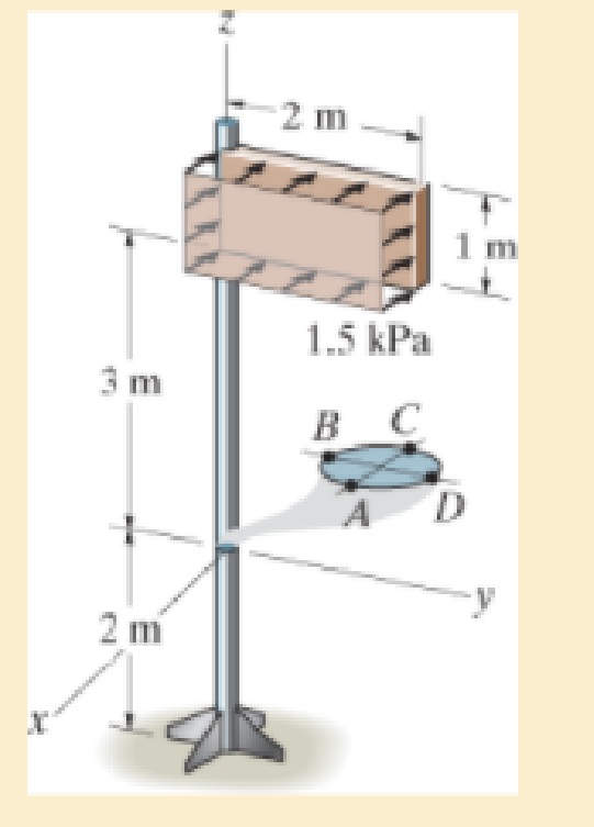
Determine the stress components at points A and B on the 100-mm-diameter supporting post. Show the results on a volume element located at each of these points.
Expert Solution & Answer
Want to see the full answer?
Check out a sample textbook solution
Students have asked these similar questions
7. A distributed load
w(x) = 4x1/3
acts on the beam AB shown in Figure 7, where x is measured in meters and w is in kN/m. The
length of the beam is L = 4 m. Find the moment of the resultant force about the point B.
w(x) per unit length
L
Figure 7
B
4. The press in Figure 4 is used to crush a small rock at E. The press comprises three links ABC,
CDE and BG, pinned to each other at B and C, and to the ground at D and G. Sketch free-body
diagrams of each component and hence determine the force exerted on the rock when a vertical
force F = 400 N is applied at A.
210
80
80
C
F
200
B
80
E
60%
-O-D
G
All dimensions in mm.
Figure 4
2. Figure 2 shows a device for lifting bricks and concrete blocks. It comprises two compo-
nents ABC and BD, with a frictionless pin at B. Determine the minimum coefficient of friction
required at A and D if the device is to work satisfactorily.
W
all dimensions in inches
Figure 2
D
Chapter 8 Solutions
MECHANICS OF MATERIALS
Ch. 8.1 - If it is subjected to an internal pressure of p =...Ch. 8.1 - If it is subjected to an internal pressure of p =...Ch. 8.1 - The thin-walled cylinder can be supported in one...Ch. 8.1 - If the inner diameter of the tank is 22 in., and...Ch. 8.1 - Air pressure in the cylinder is increased by...Ch. 8.1 - Determine the maximum force P that can be exerted...Ch. 8.1 - A boiler is constructed of 8-mm-thick steel plates...Ch. 8.1 - 88. The steel water pipe has an inner diameter of...Ch. 8.1 - The steel water pipe has an inner diameter of 12...Ch. 8.1 - The A-36-steel band is 2 in. wide and is secured...
Ch. 8.1 - The gas pipe line is supported every 20 ft by...Ch. 8.1 - A pressure-vessel head is fabricated by welding...Ch. 8.1 - An A-36-steel hoop has an inner diameter of 23.99...Ch. 8.1 - The ring, having the dimensions shown, is placed...Ch. 8.1 - The inner ring A has an inner radius r1 and outer...Ch. 8.1 - Two hemispheres having an inner radius of 2 ft and...Ch. 8.1 - In order to increase the strength of the pressure...Ch. 8.2 - Show the results on the left segment.Ch. 8.2 - Show the stress that each of these loads produce...Ch. 8.2 - Fundamental Problems F81. Determine the normal...Ch. 8.2 - Show the results in a differential element at the...Ch. 8.2 - Determine the state of stress at point A on the...Ch. 8.2 - Determine the magnitude of the load P that will...Ch. 8.2 - Determine the state of stress at point B. Show the...Ch. 8.2 - Determine the state of stress at point A on the...Ch. 8.2 - Determine the state of stress at point A on the...Ch. 8.2 - Show the results in a differential element at the...Ch. 8.2 - Determine the shortest distance d to the edge of...Ch. 8.2 - The plate has a thickness of 20 mm and P acts...Ch. 8.2 - Plot the distribution of normal stress acting...Ch. 8.2 - Also, plot the normal-stress distribution over the...Ch. 8.2 - If the allowable normal stress for the steel is...Ch. 8.2 - If the applied force P = 1.50 kip, determine the...Ch. 8.2 - Determine the maximum normal stress on the cross...Ch. 8.2 - If the wood has an allowable normal stress of...Ch. 8.2 - Determine the maximum normal stress along section...Ch. 8.2 - Sketch the stress distribution along section aa of...Ch. 8.2 - Sketch the normal-stress distribution acting over...Ch. 8.2 - Determine the state of stress at points A and B,...Ch. 8.2 - If the force of 100 N is applied to the handles,...Ch. 8.2 - Determine the stress components at point A on the...Ch. 8.2 - Determine the stress components at point B on the...Ch. 8.2 - Determine the normal stress developed at points A...Ch. 8.2 - Sketch the normal-stress distribution acting over...Ch. 8.2 - Determine the state of stress at points A and B,...Ch. 8.2 - Determine the state of stress at point A on the...Ch. 8.2 - Determine the state of stress at point B on the...Ch. 8.2 - Determine the state of stress acting at point D....Ch. 8.2 - Determine the state of stress acting at point E....Ch. 8.2 - If it is subjected to the force system shown,...Ch. 8.2 - Solve Prob.840 for point B.Ch. 8.2 - Determine the stress components acting on the...Ch. 8.2 - Determine the stress components acting on the...Ch. 8.2 - Neglect the weight of the block.Ch. 8.2 - Neglect the weight of the block.Ch. 8.2 - He is supported uniformly by two bars, each having...Ch. 8.2 - Determine the state of stress at point A, and show...Ch. 8.2 - Determine the state of stress at point B, and show...Ch. 8.2 - Determine the state of stress at point C, and show...Ch. 8.2 - Determine the maximum radius e at which the load P...Ch. 8.2 - Specify the region to which this load can be...Ch. 8.2 - Determine the smallest force P that can be applied...Ch. 8.2 - The coiled spring is subjected to a force P. If we...Ch. 8.2 - The pins at C and D are at the same location as...Ch. 8.2 - Determine the state of stress at point A, and show...Ch. 8.2 - Determine the state of stress at point B, and show...Ch. 8.2 - Determine the stress components at points A and B...Ch. 8.2 - Determine the stress components at points C and D...Ch. 8.2 - Determine the stress components in the support...Ch. 8.2 - Determine the stress components in the support...Ch. 8.2 - If the force at the ram on the clamp at D is P= 8...Ch. 8.2 - Determine the maximum ram force P that can be...Ch. 8.2 - and an outer radius of 3.00 in. If the face of the...Ch. 8.2 - for points E and F.Ch. 8.2 - Determine the stress components at points A and B...Ch. 8.2 - Solve Prob.8-65 for points C and D.Ch. 8.2 - Due to internal gearing, this causes the block to...Ch. 8.2 - Determine the state of stress at point A and show...Ch. 8.2 - Solve Prob.868 for point B.Ch. 8.2 - Determine the stress components at point A. Sketch...Ch. 8.2 - for the stress components at point B.Ch. 8.2 - Determine the state of stress at point A at...Ch. 8.2 - Determine the state of stress at point B at...Ch. 8 - If it supports a cable loading of 800 lb,...Ch. 8 - Determine the state of stress at point E on the...Ch. 8 - Determine the state of stress at point F on the...Ch. 8 - The suspender arm AE has a square cross-sectional...Ch. 8 - If the cross section of the femur at section aa...Ch. 8 - If it has a mass of 5 kg/m, determine the largest...Ch. 8 - and is used to support the vertical reactions of...Ch. 8 - and is used to support the vertical reactions of...
Knowledge Booster


Learn more about
Need a deep-dive on the concept behind this application? Look no further. Learn more about this topic, mechanical-engineering and related others by exploring similar questions and additional content below.Similar questions
- 1. The shaft AD in Figure 1 supports two pulleys at B and C of radius 200 mm and 250 mm respectively. The shaft is supported in frictionless bearings at A and D and is rotating clockwise (when viewed from the right) at a constant speed of 300 rpm. Only bearing A can support thrust. The tensions T₁ = 200 N, T₂ = 400 N, and T3 = 300 N. The distances AB = 120 mm, BC = 150 mm, and CD120 mm. Find the tension 74 and the reaction forces at the bearings. A T fo Figure 1arrow_forward5. Figure 5 shows a two-dimensional idealization of the front suspension system for a car. During cornering, the road exerts a vertical force of 5 kN and a leftward horizontal force of 1.2 kN on the tire, which is of 510 mm diameter. Draw free-body diagrams of each component and determine the forces transmitted between them. 250 A -320 B 170 D 170 -220-220- all dimensions in mm. Figure 5arrow_forward8. The force F in Figure 8 is 120 lb and the angle 0 = 25°. Find the axial force N, the shear force V and the bending moment M at the point K which is midway between B and C and illustrate their directions on a sketch of the segment KCD. E -0 B K అ D H 7 A- all dimensions in inches Figure 8 Ꮎ G Farrow_forward
- 6. Determine the coordinates x, y of the centroid of the area shaded in Figure 6. y y=x³ Figure 6 3arrow_forward3. Use the method of sections to determine the forces in the members BD, CD, CE in the struc- ture of Figure 3. A B D 4 kN 6 kN all dimensions in meters. Figure 3arrow_forwardA pipeline engineer is considering alternative natural gas pipeline routings. The first route is mostly over land and the second is primarily undersea. Both pipelines will need some valve and fitting replacements in year 25. Cost data for each route is shown in Table P2.21. Notice that the undersea route has a higher initial cost due to higher installation costs and extra corrosion protection for the pipeline. However, the undersea route has cheaper security and maintenance costs which substantially reduces annual costs. The MARR for the project is 15%. Determine which route should be pursued based on a present worth analysis.arrow_forward
- The state of stress at a point is σ = -4.00 kpsi, σy Tyz = 8.000 kpsi, and T₂ = -14.00 kpsi. What is the maximum shear stress for this case? The maximum shear stress is kpsi. = 16.00 kpsi, σ = -14.00 kpsi, Try = 11.00 kpsi,arrow_forwardThe initial cost of a proposed heat recovery system is $375,000. The annual operation andmaintenance costs are projected to be $12,000. The salvage value of the system at the end of itsuseful life (projected to be 30 years) is $60,000. The annual savings in fuel costs resulting fromthis system are estimated to be $55,000 per year.a. Assuming annual compounding, determine the rate of return for this heat recovery system.b. If management has set the MARR to be 15% for a heat recovery system like this, what is themaximum initial cost that can be spent on the system (assuming that all other costs and incomesare the same)?arrow_forwardThe initial cost of a machine for a production facility is $225,000. The machine is expected tolast for 10 years with no salvage value. The company’s tax rate is 49% and SLD is used todepreciate the machine. For this type of depreciation, the tax life of the machine is considered 8years and its salvage value is $5,000. The after-tax rate of return is 14.3%. Determine the uniformannual before-tax cash flow.arrow_forward
- Three alternatives are being considered for an air cleaning system. All three systems have a lifeof 10 years with no salvage value. System A has an initial cost of $29,000. During the first fiveyears of operation, the annual costs to operate system A are $5,000. During the second five years,the annual cost of system A increases to $16,000. System B has an initial cost of $43,000. Theannual cost to operate system B is $4,000, however, after the first year, this cost increases by$1,600 per year. System C has an initial cost of $58,000 with an annual cost of $2,400. System Crequires two upgrades: one during year 4 which costs $6,000, and the other during year 8 whichcosts $3,000. The MARR for this project is 17%. Determine which air cleaning system should beinstalled based on an economic analysis.arrow_forwardShow all work as much as you can and box out answersarrow_forwardShow as much work as possible and box out answers pleasearrow_forward
arrow_back_ios
SEE MORE QUESTIONS
arrow_forward_ios
Recommended textbooks for you
 Elements Of ElectromagneticsMechanical EngineeringISBN:9780190698614Author:Sadiku, Matthew N. O.Publisher:Oxford University Press
 Mechanics of Materials (10th Edition)Mechanical EngineeringISBN:9780134319650Author:Russell C. HibbelerPublisher:PEARSON
 Thermodynamics: An Engineering ApproachMechanical EngineeringISBN:9781259822674Author:Yunus A. Cengel Dr., Michael A. BolesPublisher:McGraw-Hill Education
 Control Systems EngineeringMechanical EngineeringISBN:9781118170519Author:Norman S. NisePublisher:WILEY
 Mechanics of Materials (MindTap Course List)Mechanical EngineeringISBN:9781337093347Author:Barry J. Goodno, James M. GerePublisher:Cengage Learning
 Engineering Mechanics: StaticsMechanical EngineeringISBN:9781118807330Author:James L. Meriam, L. G. Kraige, J. N. BoltonPublisher:WILEY
Elements Of Electromagnetics
Mechanical Engineering
ISBN:9780190698614
Author:Sadiku, Matthew N. O.
Publisher:Oxford University Press
Mechanics of Materials (10th Edition)
Mechanical Engineering
ISBN:9780134319650
Author:Russell C. Hibbeler
Publisher:PEARSON
Thermodynamics: An Engineering Approach
Mechanical Engineering
ISBN:9781259822674
Author:Yunus A. Cengel Dr., Michael A. Boles
Publisher:McGraw-Hill Education
Control Systems Engineering
Mechanical Engineering
ISBN:9781118170519
Author:Norman S. Nise
Publisher:WILEY
Mechanics of Materials (MindTap Course List)
Mechanical Engineering
ISBN:9781337093347
Author:Barry J. Goodno, James M. Gere
Publisher:Cengage Learning
Engineering Mechanics: Statics
Mechanical Engineering
ISBN:9781118807330
Author:James L. Meriam, L. G. Kraige, J. N. Bolton
Publisher:WILEY
Everything About COMBINED LOADING in 10 Minutes! Mechanics of Materials; Author: Less Boring Lectures;https://www.youtube.com/watch?v=N-PlI900hSg;License: Standard youtube license