
Concept explainers
Videos
(a) Show that the beam of Prob. 8.41 cannot be moved if the top surface of the dolly is slightly lower than the platform. (b) Show that the beam can be moved if two 175-lb workers stand on the beam at B, and determine how far to the left the beam can be moved.
8.41 A 10-ft beam, weighing 1200 lb, is to be moved to the left onto the platform as shown. A horizontal force P is applied to the dolly, which is mounted on frictionless wheels. The coefficients of friction between all surfaces are μs = 0.30 and μs = 0.25, and initially, χ = 2 ft. Knowing that the top surface of the dolly is slightly higher than the platform, determine the force P required to start moving the beam. (Hint: The beam is supported at A and D.)
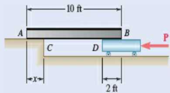
Fig. P8.41
(a)
Show that the beam cannot be moved if the top surface of the dolly is slightly lower than the platform.
Explanation of Solution
Given information:
The length of the beam is 10 ft.
The weight of the beam is
The coefficient of static friction between the surfaces is
The coefficient of kinetic friction between the surfaces is
Calculation:
Show the free-body diagram of the beam AB as in Figure 1.
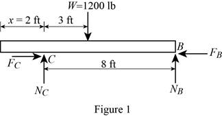
Find the normal force at point B by taking moment about end C.
Find the normal force at point C by resolving the vertical component of forces.
Find the maximum friction force at point C
Substitute 0.30 for
Find the maximum friction force at point B
Substitute 0.30 for
The maximum friction force at point B is less than the maximum friction force at point C.
The sliding is about to happen at point B.
Therefore, the beam
(b)
Show that the beam can be moved if two 175-lb workers stand on the beam at B.
Find the distance the beam moves to the left.
Answer to Problem 8.42P
The distance the beam moves to the left is
Explanation of Solution
Given information:
The length of the beam is 10 ft.
The weight of the beam is
The coefficient of static friction between the surfaces is
The coefficient of kinetic friction between the surfaces is
Calculation:
Show the free-body diagram of the beam AB as in Figure 2.
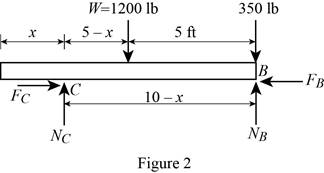
Find the normal force at point B by taking moment about end C.
Find the normal reaction at point C by taking moment about point B.
When two 175 lb workers stand on the end B:
Substitute 2 ft for x in Equation (1).
Substitute 2 ft for x in Equation (2).
Find the maximum friction force at point C
Substitute 0.30 for
Find the maximum friction force at point B
Substitute 0.30 for
The maximum friction force at point B is greater than the maximum friction force at point C.
The sliding is about to happen at point C.
Therefore, the beam
The beam will stop moving when the friction force at point C is equal to the maximum friction force at point B.
Find the friction force at point C
Substitute 0.25 for
Find the maximum friction force at point B
Substitute 0.30 for
Substitute
Therefore, the distance the beam moves to the left is
Want to see more full solutions like this?
Chapter 8 Solutions
EBK VECTOR MECHANICS FOR ENGINEERS: STA


- Qu. 13 What are the indices for the Direction 2 indicated by vector in the following sketch? Qu. 14 Determine the indices for the direction A and B shown in the following cubic unit cell. please show all work step by step from material engineeringarrow_forwardThe thin-walled open cross section shown is transmitting torque 7. The angle of twist ₁ per unit length of each leg can be determined separately using the equation 01 = 3Ti GLIC 3 where G is the shear modulus, ₁ is the angle of twist per unit length, T is torque, and L is the length of the median line. In this case, i = 1, 2, 3, and T; represents the torque in leg i. Assuming that the angle of twist per unit length for each leg is the same, show that T= Lic³ and Tmaz = G01 Cmax Consider a steel section with Tallow = 12.40 kpsi. C1 2 mm L1 20 mm C2 3 mm L2 30 mm C3 2 mm L3 25 mm Determine the torque transmitted by each leg and the torque transmitted by the entire section. The torque transmitted by the first leg is | N-m. The torque transmitted by the second leg is N-m. The torque transmitted by the third leg is N-m. The torque transmitted by the entire section is N-m.arrow_forwardPlease help, make sure it's to box out and make it clear what answers go where...arrow_forward
 Elements Of ElectromagneticsMechanical EngineeringISBN:9780190698614Author:Sadiku, Matthew N. O.Publisher:Oxford University Press
 Mechanics of Materials (10th Edition)Mechanical EngineeringISBN:9780134319650Author:Russell C. HibbelerPublisher:PEARSON
 Thermodynamics: An Engineering ApproachMechanical EngineeringISBN:9781259822674Author:Yunus A. Cengel Dr., Michael A. BolesPublisher:McGraw-Hill Education
 Control Systems EngineeringMechanical EngineeringISBN:9781118170519Author:Norman S. NisePublisher:WILEY
 Mechanics of Materials (MindTap Course List)Mechanical EngineeringISBN:9781337093347Author:Barry J. Goodno, James M. GerePublisher:Cengage Learning
 Engineering Mechanics: StaticsMechanical EngineeringISBN:9781118807330Author:James L. Meriam, L. G. Kraige, J. N. BoltonPublisher:WILEY