
MECHANICS OF MATERIALS-TEXT
9th Edition
ISBN: 2810014920922
Author: HIBBELER
Publisher: PEARSON
expand_more
expand_more
format_list_bulleted
Videos
Textbook Question
Chapter 8.1, Problem 8.15P
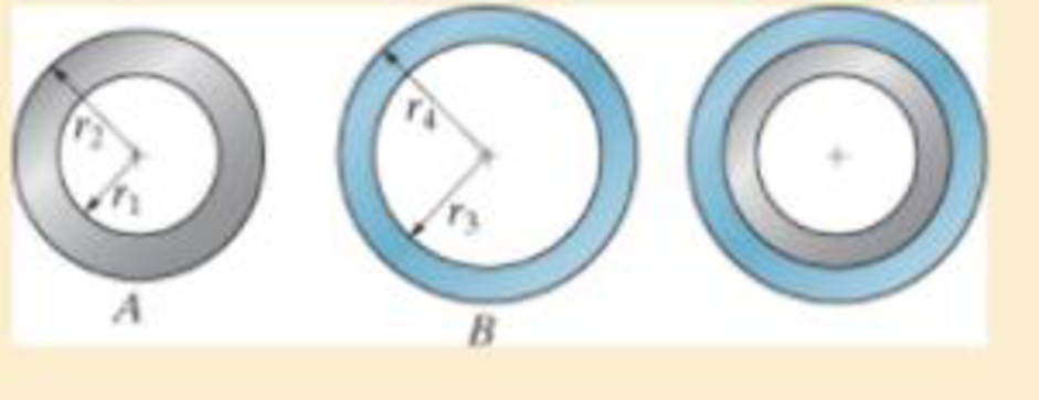
The inner ring A has an inner radius r1 and outer radius r2. The outer ring B has an inner radius r3 and an outer radius r4, and r2 > r3. If the outer ring is heated and then fitted over the inner ring, determine the pressure between the two rings when ring B reaches the temperature of the inner ring. The material has a modulus of elasticity of E and a coefficient of thermal expansion of α
 .
.
Expert Solution & Answer
Want to see the full answer?
Check out a sample textbook solution
Students have asked these similar questions
CORRECT ANSWER AND COMPLETE FBD ONLY. I PREFER HANDWRITTEN BUT ITS OKAY IF NOT. I WILL UPVOTE
2. The space truss shown is supported by ball-and-socket joints at A, B and C. Factored loads P1 and P2 areacting on joints D and E, respectively, towards the negative y-direction.
1. Calculate the stress of member CE, indicate tension or compression. Answer: 23.61 MPa Tension2. Calculate the stress of member AD, indicate tension or compression. Answer: 21.01 MPa Compression3. Calculate the stress of member CD, indicate tension or compression. Answer: 11.03 MPa Tension
CORRECT ANSWER AND COMPLETE FBD ONLY. I PREFER HANDWRITTEN BUT ITS OKAY IF NOT. I WILL UPVOTE
3. The frame has pin supports at A and E, subject to a wind load. Treat joint C to be an internal hinge.
Given:Dimensions, H1 = 3.0 m; H2 = 4.5 m; L = 10.0 mWind loads, wWL (AB) = 4.8 kN/m; wWL (BC) = 3.9 kN/m; wWL (CD) = 1.5 kN/m; wWL (DE) = 1.2 kN/mMembers are made of A36 steel Wide Flange Section with the following properties:Area, A = 64000 mm2Depth, d = 762 mmFlange width, bf = 371 mmThickness of web, tw = 32 mmThickness of flange, tf = 57.9 mmMoment of inertia about x-axis, Ix = 6080 x 106 mm4The wide flange is oriented so that the bending is about the x-axis1. Calculate the stress in member AB, due to the axial load it carries, indicate if tension or compression.Answer: 0.0476 MPa Tension2. Calculate the stress in member DE, due to the axial load it carries, indicate if tension or compression.Answer: 0.2351 MPa Compression3. Calculate the maximum bending stress at B. Answer: 4.282 MPa
32 mm
32 mm
b'
c'
C
32 mm
32 mm
b
PROBLEM 6.41
a
The extruded beam shown has a uniform wall thickness of 3 mm. Knowing that
the vertical shear in the beam is 9 kN, determine the shearing stress at each of the
five points indicated.
Chapter 8 Solutions
MECHANICS OF MATERIALS-TEXT
Ch. 8.1 - If it is subjected to an internal pressure of p =...Ch. 8.1 - If it is subjected to an internal pressure of p =...Ch. 8.1 - The thin-walled cylinder can be supported in one...Ch. 8.1 - If the inner diameter of the tank is 22 in., and...Ch. 8.1 - Prob. 8.5PCh. 8.1 - 8–6. If the flow of water within the pipe in Prob....Ch. 8.1 - A boiler is constructed of 8-mm-thick steel plates...Ch. 8.1 - 88. The steel water pipe has an inner diameter of...Ch. 8.1 - The steel water pipe has an inner diameter of 12...Ch. 8.1 - The A-36-steel band is 2 in. wide and is secured...
Ch. 8.1 - Two hemispheres having an inner radius of 2 ft and...Ch. 8.1 - A pressure-vessel head is fabricated by welding...Ch. 8.1 - An A-36-steel hoop has an inner diameter of 23.99...Ch. 8.1 - The ring, having the dimensions shown, is placed...Ch. 8.1 - The inner ring A has an inner radius r1 and outer...Ch. 8.1 - *8–16. A closed-ended pressure vessel is...Ch. 8.1 - In order to increase the strength of the pressure...Ch. 8.2 - Show the results on the left segment.Ch. 8.2 - Show the stress that each of these loads produce...Ch. 8.2 - Fundamental Problems F81. Determine the normal...Ch. 8.2 - Show the results in a differential element at the...Ch. 8.2 - Determine the state of stress at point A on the...Ch. 8.2 - Determine the magnitude of the load P that will...Ch. 8.2 - Determine the state of stress at point B. Show the...Ch. 8.2 - Determine the state of stress at point A on the...Ch. 8.2 - Determine the state of stress at point A on the...Ch. 8.2 - Show the results in a differential element at the...Ch. 8.2 - Determine the shortest distance d to the edge of...Ch. 8.2 - 8–19. Determine the maximum and minimum normal...Ch. 8.2 - *8–20. Determine the maximum and minimum normal...Ch. 8.2 - Also, plot the normal-stress distribution over the...Ch. 8.2 - 8–22. The clamp is made from members AB and AC,...Ch. 8.2 - 8–23. The clamp is made from members AB and AC,...Ch. 8.2 - Prob. 8.24PCh. 8.2 - 8–25. The bearing pin supports the load of 700 lb....Ch. 8.2 - Determine the maximum normal stress on the cross...Ch. 8.2 - If the wood has an allowable normal stress of...Ch. 8.2 - *8–28. The cylindrical post, having a diameter of...Ch. 8.2 - 8–29. Determine the maximum load P that can be...Ch. 8.2 - If the force of 100 N is applied to the handles,...Ch. 8.2 - 8–31. Determine the smallest distance d to the...Ch. 8.2 - *8–32. The horizontal force of P = 80 kN acts at...Ch. 8.2 - 8–33. The control lever is subjected to a...Ch. 8.2 - 8–34. The control lever is subjected to a...Ch. 8.2 - 8–35. The tubular shaft of the soil auger is...Ch. 8.2 - Determine the state of stress at point A on the...Ch. 8.2 - Determine the state of stress at point B on the...Ch. 8.2 - Determine the state of stress acting at point D....Ch. 8.2 - Determine the state of stress acting at point E....Ch. 8.2 - Prob. 8.40PCh. 8.2 - Prob. 8.41PCh. 8.2 - 8–42. Determine the state of stress at point A on...Ch. 8.2 - 8–43. Determine the state of stress at point B on...Ch. 8.2 - Neglect the weight of the block.Ch. 8.2 - Neglect the weight of the block.Ch. 8.2 - Prob. 8.46PCh. 8.2 - Prob. 8.47PCh. 8.2 - Prob. 8.48PCh. 8.2 - Prob. 8.49PCh. 8.2 - The coiled spring is subjected to a force P. If we...Ch. 8.2 - Specify the region to which this load can be...Ch. 8.2 - Determine the smallest force P that can be applied...Ch. 8.2 - 8–53. The 1-in.-diameter rod is subjected to the...Ch. 8.2 - 8–54. The 1-in.-diameter rod is subjected to the...Ch. 8.2 - 8–55. Determine the state of stress at point A on...Ch. 8.2 - *8–56. Determine the state of stress at point B on...Ch. 8.2 - Determine the stress components at points A and B...Ch. 8.2 - Determine the stress components at points C and D...Ch. 8.2 - 8–59. If P = 60 kN, determine the maximum normal...Ch. 8.2 - *8–60. Determine the maximum allowable force P, if...Ch. 8.2 - If the force at the ram on the clamp at D is P= 8...Ch. 8.2 - Determine the maximum ram force P that can be...Ch. 8.2 - and an outer radius of 3.00 in. If the face of the...Ch. 8.2 - for points E and F.Ch. 8.2 - 8–65. Determine the state of stress at point A on...Ch. 8.2 - 8–66. Determine the state of stress at point B on...Ch. 8.2 - 8–67. The metal link is subjected to the axial...Ch. 8.2 - *8–68. The bar has a diameter of 40 mm. If it is...Ch. 8.2 - 8–69. Solve Prob. 8-68 for point B.
Ch. 8.2 - Determine the stress components at point A. Sketch...Ch. 8.2 - for the stress components at point B.Ch. 8.2 - Determine the state of stress at point A at...Ch. 8.2 - Determine the state of stress at point B at...Ch. 8 - If it supports a cable loading of 800 lb,...Ch. 8 - Determine the state of stress at point E on the...Ch. 8 - Determine the state of stress at point F on the...Ch. 8 - If it has a mass of 5 kg/m, determine the largest...Ch. 8 - 8–78. Solve Prob. 8–77 if the bar has a circular...Ch. 8 - The suspender arm AE has a square cross-sectional...Ch. 8 - Prob. 8.80RPCh. 8 - 8–81. The hydraulic cylinder has an inner diameter...Ch. 8 - If the cross section of the femur at section aa...Ch. 8 - 8-83. Air pressure in the cylinder is increased by...Ch. 8 - *8-84. Determine the maximum force P that can be...Ch. 8 - and is used to support the vertical reactions of...Ch. 8 - and is used to support the vertical reactions of...
Knowledge Booster


Learn more about
Need a deep-dive on the concept behind this application? Look no further. Learn more about this topic, mechanical-engineering and related others by exploring similar questions and additional content below.Similar questions
- In a structural reliability problem, the resistance (capacity) R and load effect (demand) S random variables associated with a failure mode of the structure of interest are normally distributed and statistically independent with the following probability distribution parameters (or statistics) in consistent units: MR = 12, σR = 3 μs = 5, σs = 2 (a) Determine the exact probability of failure pF ·arrow_forwardThe resistance R and load effect S for a given failure mode are statistically independent random variables with marginal PDF's 1 fR (r) = 0≤r≤100 100' fs(s)=0.05e-0.05s (a) Determine the probability of failure by computing the probability content of the failure domain defined as {rarrow_forwardPlease solve this problem as soon as possible My ID# 016948724arrow_forwardThe gears shown in the figure have a diametral pitch of 2 teeth per inch and a 20° pressure angle. The pinion rotates at 1800 rev/min clockwise and transmits 200 hp through the idler pair to gear 5 on shaft c. What forces do gears 3 and 4 transmit to the idler shaft? TS I y 18T 32T This a 12 x 18T C 48T 5arrow_forwardQuestion 1. Draw 3 teeth for the following pinion and gear respectively. The teeth should be drawn near the pressure line so that the teeth from the pinion should mesh those of the gear. Drawing scale (1:1). Either a precise hand drawing or CAD drawing is acceptable. Draw all the trajectories of the involute lines and the circles. Specification: 18tooth pinion and 30tooth gear. Diameter pitch=P=6 teeth /inch. Pressure angle:20°, 1/P for addendum (a) and 1.25/P for dedendum (b). For fillet, c=b-a.arrow_forward5. The figure shows a gear train. There is no friction at the bearings except for the gear tooth forces. The material of the milled gears is steel having a Brinell hardness of 170. The input shaft speed (n2) is 800 rpm. The face width and the contact angle for all gears are 1 in and 20° respectively. In this gear set, the endurance limit (Se) is 15 kpsi and nd (design factor) is 2. (a) Find the revolution speed of gear 5. (b) Determine whether each gear satisfies the design factor of 2.0 for bending fatigue. (c) Determine whether each gear satisfies the design factor of 2.0 for surface fatigue (contact stress). (d) According to the computation results of the questions (b) and (c), explain the possible failure mechanisms for each gear. N4=28 800rpm N₁=43 N5=34 N₂=14 P(diameteral pitch)=8 for all gears Coupled to 2.5hp motorarrow_forward1. The rotating steel shaft is simply supported by bearings at points of B and C, and is driven by a spur gear at D, which has a 6-in pitch diameter. The force F from the drive gear acts at a pressure angle of 20°. The shaft transmits a torque to point A of TA =3000 lbĘ in. The shaft is machined from steel with Sy=60kpsi and Sut=80 kpsi. (1) Draw a shear force diagram and a bending moment diagram by F. According to your analysis, where is the point of interest to evaluate the safety factor among A, B, C, and D? Describe the reason. (Hint: To find F, the torque Tд is generated by the tangential force of F (i.e. Ftangential-Fcos20°) When n=2.5, K=1.8, and K₁ =1.3, determine the diameter of the shaft based on (2) static analysis using DE theory (note that fatigue stress concentration factors need to be used for this question because the loading condition is fatigue) and (3) a fatigue analysis using modified Goodman. Note) A standard diameter is not required for the questions. 10 in Darrow_forward3 N2=28 P(diametral pitch)=8 for all gears Coupled to 25 hp motor N3=34 Full depth spur gears with pressure angle=20° N₂=2000 rpm (1) Compute the circular pitch, the center-to-center distance, and base circle radii. (2) Draw the free body diagram of gear 3 and show all the forces and the torque. (3) In mounting gears, the center-to-center distance was reduced by 0.1 inch. Calculate the new values of center-to-center distance, pressure angle, base circle radii, and pitch circle diameters. (4)What is the new tangential and radial forces for gear 3? (5) Under the new center to center distance, is the contact ratio (mc) increasing or decreasing?arrow_forward2. A flat belt drive consists of two 4-ft diameter cast-iron pulleys spaced 16 ft apart. A power of 60 hp is transmitted by a pulley whose speed is 380 rev/min. Use a service factor (Ks) pf 1.1 and a design factor 1.0. The width of the polyamide A-3 belt is 6 in. Use CD=1. Answer the following questions. (1) What is the total length of the belt according to the given geometry? (2) Find the centrifugal force (Fc) applied to the belt. (3) What is the transmitted torque through the pulley system given 60hp? (4) Using the allowable tension, find the force (F₁) on the tight side. What is the tension at the loose side (F2) and the initial tension (F.)? (5) Using the forces, estimate the developed friction coefficient (f) (6) Based on the forces and the given rotational speed, rate the pulley set. In other words, what is the horse power that can be transmitted by the pulley system? (7) To reduce the applied tension on the tight side, the friction coefficient is increased to 0.75. Find out the…arrow_forwardThe tooth numbers for the gear train illustrated are N₂ = 24, N3 = 18, №4 = 30, №6 = 36, and N₁ = 54. Gear 7 is fixed. If shaft b is turned through 5 revolutions, how many turns will shaft a make? a 5 [6] barrow_forwardCE-112 please solve this problem step by step and give me the correct answerarrow_forwardCE-112 please solve this problem step by step and give me the correct answerarrow_forwardarrow_back_iosSEE MORE QUESTIONSarrow_forward_ios
Recommended textbooks for you
 Mechanics of Materials (MindTap Course List)Mechanical EngineeringISBN:9781337093347Author:Barry J. Goodno, James M. GerePublisher:Cengage Learning
 International Edition---engineering Mechanics: St...Mechanical EngineeringISBN:9781305501607Author:Andrew Pytel And Jaan KiusalaasPublisher:CENGAGE L
 Principles of Heat Transfer (Activate Learning wi...Mechanical EngineeringISBN:9781305387102Author:Kreith, Frank; Manglik, Raj M.Publisher:Cengage Learning
 Refrigeration and Air Conditioning Technology (Mi...Mechanical EngineeringISBN:9781305578296Author:John Tomczyk, Eugene Silberstein, Bill Whitman, Bill JohnsonPublisher:Cengage Learning
Mechanics of Materials (MindTap Course List)
Mechanical Engineering
ISBN:9781337093347
Author:Barry J. Goodno, James M. Gere
Publisher:Cengage Learning
International Edition---engineering Mechanics: St...
Mechanical Engineering
ISBN:9781305501607
Author:Andrew Pytel And Jaan Kiusalaas
Publisher:CENGAGE L
Principles of Heat Transfer (Activate Learning wi...
Mechanical Engineering
ISBN:9781305387102
Author:Kreith, Frank; Manglik, Raj M.
Publisher:Cengage Learning
Refrigeration and Air Conditioning Technology (Mi...
Mechanical Engineering
ISBN:9781305578296
Author:John Tomczyk, Eugene Silberstein, Bill Whitman, Bill Johnson
Publisher:Cengage Learning
Material Properties 101; Author: Real Engineering;https://www.youtube.com/watch?v=BHZALtqAjeM;License: Standard YouTube License, CC-BY
Mechanical Properties of Materials; Author: Academic Gain Tutorials;https://www.youtube.com/watch?v=6L-r3hx0NLM;License: Standard Youtube License