
Concept explainers
Videos
Find the values of S and Z and the shape factor about the horizontal x—x axes, for the sections shown in the accompanying figures.
8-1.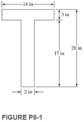
The values of S and Z and the shape factor about the horizontal x-x axes for the given section.
Answer to Problem 8.1PFS
Explanation of Solution
The cross-section is shown below:
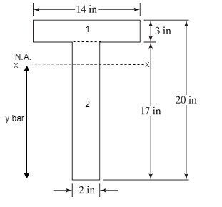
The depth of neutral axis from bottom is given by
The area of both section 1 and section 2 are
The depth of centre of gravity both section 1 and section 2 are
Now, substituting the values in equation (1),
The distance of centre of gravity from section 1 from the Neutral Axis (N.A.) is
The distance of centre of gravity from section 2 from the Neutral Axis (N.A.) is
The moment of inertia is
The elastic section modulus is
The location of plastic neutral axis is
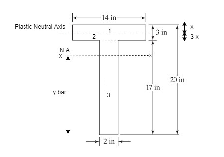
The area of flange is greater than the half of the sectional area. Hence the plastic neutral axis is located within the flange as shown in the above figure.
The depth of plastic neutral axis from top of the section x is
The area of both section 1 and section 2 are
The depths of centre of gravity both section 1 and section 2 from plastic neutral axis are
The plastic section modulus is
The shape factor is
Conclusion:
The values of S and Z and the shape factor about the horizontal x-x axes are
Want to see more full solutions like this?
Chapter 8 Solutions
Structural Steel Design (6th Edition)


- 4. Use the influence function method to draw the influence line for the shear just to the right of A. Assume C is fixed, A is a roller, and B is a pin. 8 ft A 16 ft B 10 ft-arrow_forward4-39. Draw the shear and moment diagrams for each of the three members of the frame. Assume the frame is pin connected at A, C, and D and there is a fixed joint at B. 4 m 50 kN 40 kN -1.5 m -2 m 1.5 B 15 kN/m 6 m Darrow_forwardAggregates from three sources having the properties shown in Table P5.41were blended at a ratio of 25:60:15 by weight. Determine the properties of theaggregate blend.arrow_forward
- 7-7. Determine the equations of the elastic curve for the beam using the x and x, coordinates. Specify the beam's maximum deflection. El is constant. 22arrow_forwardThe cantilever beam shown below supports a uniform service (unfactored) dead load of 1.5 kip/ft plus its own self weight, plus two unknown concentrated service (unfactored) live loads, as shown. The concrete has f’c = 6,000 psi and the steel yield strength is 60 ksi. a. Determine the design moment capacity. b. Set up the applied bending moment capacity. c. Calculate maximum safe concentrated live load that the beam may carry.arrow_forwardThe circular slab of radius r supported by four columns, as shown in figure, is to be isotropically reinforced. Find the ultimate resisting moment (m) per linear meter required just to sustain a concentrated factored load of P kN applied at the center of the slab. Solve by using equilibrium m m Columnarrow_forward
- By using the yield line theory, determine the ultimate resisting moment per linear meter (m) for an isotropic reinforced concrete two-way simply supported polygon slab shown in figure under a uniform load (q). Solve by using equilibrium method m marrow_forwardBy using the yield line theory, determine the ultimate resisting moment per linear meter (m) for an isotropic reinforced concrete two-way simply supported polygon slab shown in figure under a concentrated factored load of P. Solve by Using equilibrium method m m 8/arrow_forwardH.W: Evaluate the integral 1. 30 √ · √(x²y – 2xy)dydx 0-2 3 1 3. (2x-4y)dydx 1-1 2π π 5. (sinx + cosy)dxdy π 0 0 1 ƒ ƒ (x + 2. +y+1)dxdy 4. -1-1 41 ][ 20 x²ydxdyarrow_forward
- Example 5 By using the yield line theory, determine the moment (m) for an isotropic reinforced concrete two-way slab (supports on two S.S sides shown in figure under the load (P) (all dimensions are in mm). Solve by using equilibrium method Please solve by using equilibrium method m m 3000 2000 2000arrow_forward2. During construction, gate AB is temporarily held in place by the horizontal strut CD. Determine the force in the strut CD, if the gate is 3.0-m wide. A 0 B D Density of water = 103 kg/m³ 2 m 3 marrow_forward5. A gate is used to hold water as shown. The gate is rectangular and is 8-ft wide. Neglect the weight of the gate. Determine at what depth the gate is just about to open. 5000 Ib 15 ft Hinge 60°arrow_forward
 Fundamentals Of Construction EstimatingCivil EngineeringISBN:9781337399395Author:Pratt, David J.Publisher:Cengage,
 Architectural Drafting and Design (MindTap Course...Civil EngineeringISBN:9781285165738Author:Alan Jefferis, David A. Madsen, David P. MadsenPublisher:Cengage Learning
 Materials Science And Engineering PropertiesCivil EngineeringISBN:9781111988609Author:Charles GilmorePublisher:Cengage Learning
 Residential Construction Academy: House Wiring (M...Civil EngineeringISBN:9781285852225Author:Gregory W FletcherPublisher:Cengage Learning
 Steel Design (Activate Learning with these NEW ti...Civil EngineeringISBN:9781337094740Author:Segui, William T.Publisher:Cengage Learning
 Engineering Fundamentals: An Introduction to Engi...Civil EngineeringISBN:9781305084766Author:Saeed MoaveniPublisher:Cengage Learning