
Videos
Positive-sequence components consist of three phasors _________ with magnitudes and _________ phase displacement in positive sequence; negative- sequence components consist of three phasors with ________ magnitudes and _________ phase displacement in negative sequence; and zero-sequence components consist of three phasors with __________ magnitudes and __________ phase displacement.
To fill: The appropriate words in the given blank spaces.
Answer to Problem 8.1MCQ
The appropriate words are: equal,
Explanation of Solution
The method of symmetrical components is used to solve the unbalanced system. This method is also termed as three-component method. The balanced set of components are positive sequence component, negative sequence component and zero-sequence component.
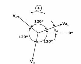
Positive Sequence components: The positive-sequence system is represented by a balanced system of phasors having the same phase sequence (and therefore positive phase rotation) as the original unbalanced system. The phasors of the positive-sequence system are equal in magnitude and displaced from each other by
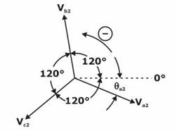
Negative Sequence components: The negative-sequence system is represented by a balanced system of phasors having the opposite phase sequence (and therefore negative phase rotation) to the original system. The phasors of the negative-sequence system are also equal in magnitude and displaced from each other by
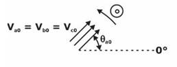
Zero Sequence components: The zero-sequence system is represented by three single phasors that are equal in magnitude and angular displacement between all the phasors is
Therefore, in positive-sequence component, there are three phasors of equal magnitude but
Want to see more full solutions like this?
Chapter 8 Solutions
Power System Analysis & Design


- 4. Develop the relationship between the output voltage Vout and the input voltage for the circuit below. Di R R Vout +arrow_forwardPlease solve this question step by step handwritten solution and do not use chat gpt or other ai tools thank youarrow_forwardPlease solve this questions step by step detailed and handwritten, do not use chat gpt or other ai tools thanks!arrow_forward
- Please solve this questions step by step detailed and handwritten, do not use chat gpt or other ai tools thanks!arrow_forwardPlease solve this question step by step with explanation and handwritten solution please do not use chat gpt or other ai tools thanksarrow_forwardPlease solve this question fully step by step handwritten and do not use chat gpt or any ai tools thanksarrow_forward
- Please solve this question step by step hand written solution and do not use chat gpt or any ai tools thanks!arrow_forwardPlease Solve this question step by step handwritten solution and do not use chat gpt or any ai tools thanks!arrow_forwardPlease solve this question step by step handrwitten solution and do not use chat gpt or any ai tools thanks.arrow_forward
 Power System Analysis and Design (MindTap Course ...Electrical EngineeringISBN:9781305632134Author:J. Duncan Glover, Thomas Overbye, Mulukutla S. SarmaPublisher:Cengage Learning