
Engineering Circuit Analysis
9th Edition
ISBN: 9780073545516
Author: Hayt, William H. (william Hart), Jr, Kemmerly, Jack E. (jack Ellsworth), Durbin, Steven M.
Publisher: Mcgraw-hill Education,
expand_more
expand_more
format_list_bulleted
Concept explainers
Videos
Textbook Question
Chapter 8, Problem 60E
For the circuit given in Fig. 8.85, (a) determine vL(0−), vL(0+), iL(0−), and iL(0+); (b) calculate iL(150 ns). (c) Verify your answer to part (b) with an appropriate SPICE simulation.
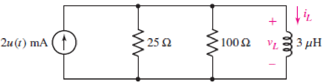
■ FIGURE 8.85
Expert Solution & Answer
Want to see the full answer?
Check out a sample textbook solution
Students have asked these similar questions
1°
⑤
Aa
"Human-written solution required"
2. Using the characteristics of Fig. 6.11, determine ID for the following levels of VGs (with
VDS > VP):
a. VGs = 0V.
b. VGs=-1 V.
c. VGs -1.5 V.
d. VGS
-1.8 V.
e. VGS = -4 V.
f. VGs=-6V.
3. Using the results of problem 2 plot the transfer characteristics of ID vs. VGS-
4. a. Determine Vps for VGs = 0V and Ip = 6 mA using the characteristics of Fig. 6.11.
b. Using the results of part (a), calculate the resistance of the JFET for the region Ip = 0 to
6 mA for VGs =0V.
c. Determine Vps for VGS = -1 V and ID = 3 mA.
d. Using the results of part (c), calculate the resistance of the JFET for the region ID = 0 to
3 mA for VGs -1 V.
e. Determine Vps for VGs = -2 V and ID = 1.5 mA.
f. Using the results of part (e), calculate the resistance of the JFET for the region ID = 0 to
1.5 mA for VGS-2 V.
g. Defining the result of part (b) as ro, determine the resistance for VGs -1 V using
Eq. (6.1) and compare with the results of part (d).
h. Repeat part (g)…
①
Esterfication
+ R'on
R
Hydrolysis
OH
Alcohol
A.
0-R
Carboxylic
Acid
Ester
NOD-10
4. a. Determine VDs for VGS = 0 V and ID = 6 mA using the characteristics of Fig. 6.11.
b. Using the results of part (a), calculate the resistance of the JFET for the region ID = 0 to
6 mA for VGS = 0 V.
c. Determine VDs for VGS = -1 V and ID = 3 mA.
d. Using the results of part (c), calculate the resistance of the JFET for the region ID = 0 to
3 mA for VGS = -1 V.
e. Determine VDs for VGS = -2 V and ID = 1.5 mA.
f. Using the results of part (e), calculate the resistance of the JFET for the region ID = 0 to
1.5 mA for VGS = -2 V.
g. Defining the result of part (b) as ro, determine the resistance for VGS = -1 V using
Eq. (6.1) and compare with the results of part (d).
h. Repeat part (g) for VGS = -2 V using the same equation, and compare the results with part (f).
i. Based on the results of parts (g) and (h), does Eq. (6.1) appear to be a valid approximation?
Chapter 8 Solutions
Engineering Circuit Analysis
Ch. 8.1 - For the circuit in Fig. 8.2, what value of...Ch. 8.1 - Noting carefully how the circuit changes once the...Ch. 8.2 - In a source-free series RC circuit, find the...Ch. 8.3 - Prob. 4PCh. 8.3 - Prob. 5PCh. 8.4 - Prob. 6PCh. 8.4 - Prob. 7PCh. 8.4 - Prob. 8PCh. 8.5 - Evaluate each of the following at t = 0.8: (a)...Ch. 8.6 - For the circuit of Fig. 8.37, find vc(t) at t...
Ch. 8.7 - Prob. 11PCh. 8.7 - The voltage source 60 40u(t) V is in series with...Ch. 8.7 - Prob. 13PCh. 8.8 - Prob. 14PCh. 8.8 - Prob. 15PCh. 8 - A source-free RC circuit has R = 4 k and C = 22 F,...Ch. 8 - A source-free RC circuit has v(0) = 12 V and R =...Ch. 8 - The resistor in the circuit of Fig. 8.51 has been...Ch. 8 - Prob. 4ECh. 8 - Prob. 5ECh. 8 - Prob. 6ECh. 8 - Prob. 7ECh. 8 - Prob. 8ECh. 8 - Prob. 9ECh. 8 - The switch in Fig. 8.56 has been closed for a long...Ch. 8 - For the circuit in Fig. 8.56, find (a) the total...Ch. 8 - Design a capacitor-based circuit that can achieve...Ch. 8 - (a) Graph the function f (t) = 10e2t over the...Ch. 8 - The current i(t) flowing through a 1 k resistor is...Ch. 8 - Radiocarbon dating has a similar exponential time...Ch. 8 - For the circuit of Fig. 8.4, compute the time...Ch. 8 - Design a circuit which will produce a current of 1...Ch. 8 - Prob. 18ECh. 8 - Prob. 19ECh. 8 - Referring to the circuit shown in Fig. 8.11,...Ch. 8 - Prob. 21ECh. 8 - With the assumption that the switch in the circuit...Ch. 8 - The switch in Fig. 8.57 has been closed since...Ch. 8 - The switch in the circuit of Fig. 8.58 has been...Ch. 8 - Assuming the switch initially has been open for a...Ch. 8 - (a) Obtain an expression for v(t), the voltage...Ch. 8 - For the circuit of Fig. 8.61, determine ix, iL,...Ch. 8 - Prob. 28ECh. 8 - Prob. 29ECh. 8 - Prob. 30ECh. 8 - Prob. 31ECh. 8 - (a) Obtain an expression for vx as labeled in the...Ch. 8 - Prob. 33ECh. 8 - Prob. 34ECh. 8 - Prob. 35ECh. 8 - Prob. 36ECh. 8 - Prob. 37ECh. 8 - The switch in Fig. 8.70 is moved from A to B at t...Ch. 8 - Prob. 39ECh. 8 - Prob. 40ECh. 8 - Evaluate the following functions at t = 1, 0, and...Ch. 8 - Prob. 42ECh. 8 - Prob. 43ECh. 8 - Prob. 44ECh. 8 - You can use MATLAB to represent the unit-step...Ch. 8 - With reference to the circuit depicted in Fig....Ch. 8 - For the circuit given in Fig. 8.75, (a) determine...Ch. 8 - Prob. 48ECh. 8 - Prob. 49ECh. 8 - You build a portable solar charging circuit...Ch. 8 - The switch in the circuit of Fig. 8.78 has been...Ch. 8 - The switch in the circuit of Fig. 8.78 has been...Ch. 8 - Prob. 53ECh. 8 - Prob. 54ECh. 8 - Prob. 55ECh. 8 - For the circuit represented in Fig. 8.82, (a)...Ch. 8 - Prob. 58ECh. 8 - Prob. 59ECh. 8 - For the circuit given in Fig. 8.85, (a) determine...Ch. 8 - The circuit depicted in Fig. 8.86 contains two...Ch. 8 - Prob. 62ECh. 8 - Prob. 63ECh. 8 - A series RL circuit has a voltage that steps from...Ch. 8 - For the two-source circuit of Fig. 8.89, note that...Ch. 8 - (a) Obtain an expression for iL as labeled in Fig....Ch. 8 - Obtain an expression for i(t) as labeled in the...Ch. 8 - Obtain an expression for i1 as indicated in Fig....Ch. 8 - Plot the current i(t) in Fig. 8.93 if (a) R = 10 ;...Ch. 8 - A dc motor can be modeled as a series RL circuit...Ch. 8 - Prob. 71ECh. 8 - Prob. 72ECh. 8 - A series RC sequentially switched circuit has R =...Ch. 8 - Refer to the circuit of Fig. 8.95, which contains...Ch. 8 - In the circuit of Fig. 8.95, a 3 mF capacitor is...Ch. 8 - Prob. 78E
Knowledge Booster


Learn more about
Need a deep-dive on the concept behind this application? Look no further. Learn more about this topic, electrical-engineering and related others by exploring similar questions and additional content below.Similar questions
- A. Using D flip-flops, design a logic circuit for the finite-state machine described by the state assigned table in Fig. 1. Present Next State State Output x=0 x=1 Y2Y1 Y2Y1 YY Z 00 00 01 0 01 10 11 888 00 10 0 00 10 1 00 10 1 Fig. 1arrow_forwardAthree phase a.c. distributor AB has: A B C The distance from A to B is 500 m. The distance from A to C is 800 m. The impedance of each section is (6+j 8) /km. The voltage at the far end is maintained at 250 volt. Find: sending voltage, sending current, supply power factor and 80A 60 A total voltage drop. 0.8 lag. P.f 0.6 lead. p.farrow_forwardengineering electromagnetics Subjectarrow_forward
- a ADI ADI b Co ADDS D Fig.(2) 2-For resistive load, measure le output voltage by using oscilloscope; then sketch this wave. 3- Measure the average values ::f V₁ and IL: 4- Repeat steps 2 & 3 but for PL load.arrow_forwardDetermine the type of media In a certain medium with µ = o, & = 40 H = 12ely sin(x x 10% - By) a, A/m A plane wave propagating through a medium with ɛ, = 8, μ, = 2 has E = 0.5 3sin(10°t - Bz) a, V/m. Determine In a certain medium - E = 10 cos (2 x 10't ẞx)(a, + a.) V/m If μ == 50μo, & = 2ɛ, and o = 0, In a medium, -0.05x E=16e sin (2 x 10% -2x) a₂ V/marrow_forward"How can I know if it's lossless or lossy? Is there an easy way?" A plane wave propagating through a medium with &,,-8 μr = 2 nas: E = 0.5 ej0.33z sin (10' t - ẞz) ax V/m. A plane wave in non- · (Mr=1) has: magnetic medium E. 50 sin (10st + 27 ) ay v/m =arrow_forward
- a A DI AD: AD, b C ADDS AD Fig.(2) LOIT 4-Draw the waveform for the c:t. shown in fig.(2) but after replaced Di and D3 by thyristors with a 30° and a2 #90°.arrow_forwarda b C ADDS D Fig.(2) L O 5- Draw the waveform for the cct. shown in fig.(2) but after replace the 6-diodes by 6- thyristor.arrow_forwardThe magnetic field component of an EM wave propagating through a nonmagnetic medium (po) is = Determine: H=25 sin (2 x 10't + 6x) a, mA/m (a) The direction of wave propagation. (b) The permittivity of the medium. (c) The electric field intensity.arrow_forward
- In a certain medium with μo, & = H 12e 480 y sin (x x 10% By) a, A/m find: (a) the wave period T, (b) the wavelength A, (c) the electric field E, (d) the phase difference between E and H.arrow_forwardA plane wave propagating through a medium with ɛ, = 8, μ, 2 has E = 0.5 e-3 sin(108tẞz) a, V/m. Determine (a) B (b) The loss tangent (c) Wave impedance (d) Wave velocity (e) H field Answer: (a) 1.374 rad/m, (b) 0.5154, (c) 177.72 /13.63° 2, (d) 7.278 × 10⁷ m/s, (e) 2.817e3sin(108 - Bz - 13.63°)a, mA/m.arrow_forwardIn a nonmagnetic medium, E = 50 cos (10% - 8x) a, + 40 sin (10't - 8x) a, V/m find the dielectric constant &, and the corresponding H.arrow_forward
arrow_back_ios
SEE MORE QUESTIONS
arrow_forward_ios
Recommended textbooks for you
 Introductory Circuit Analysis (13th Edition)Electrical EngineeringISBN:9780133923605Author:Robert L. BoylestadPublisher:PEARSON
 Delmar's Standard Textbook Of ElectricityElectrical EngineeringISBN:9781337900348Author:Stephen L. HermanPublisher:Cengage Learning
 Programmable Logic ControllersElectrical EngineeringISBN:9780073373843Author:Frank D. PetruzellaPublisher:McGraw-Hill Education
 Fundamentals of Electric CircuitsElectrical EngineeringISBN:9780078028229Author:Charles K Alexander, Matthew SadikuPublisher:McGraw-Hill Education
 Electric Circuits. (11th Edition)Electrical EngineeringISBN:9780134746968Author:James W. Nilsson, Susan RiedelPublisher:PEARSON
 Engineering ElectromagneticsElectrical EngineeringISBN:9780078028151Author:Hayt, William H. (william Hart), Jr, BUCK, John A.Publisher:Mcgraw-hill Education,
Introductory Circuit Analysis (13th Edition)
Electrical Engineering
ISBN:9780133923605
Author:Robert L. Boylestad
Publisher:PEARSON
Delmar's Standard Textbook Of Electricity
Electrical Engineering
ISBN:9781337900348
Author:Stephen L. Herman
Publisher:Cengage Learning
Programmable Logic Controllers
Electrical Engineering
ISBN:9780073373843
Author:Frank D. Petruzella
Publisher:McGraw-Hill Education
Fundamentals of Electric Circuits
Electrical Engineering
ISBN:9780078028229
Author:Charles K Alexander, Matthew Sadiku
Publisher:McGraw-Hill Education
Electric Circuits. (11th Edition)
Electrical Engineering
ISBN:9780134746968
Author:James W. Nilsson, Susan Riedel
Publisher:PEARSON
Engineering Electromagnetics
Electrical Engineering
ISBN:9780078028151
Author:Hayt, William H. (william Hart), Jr, BUCK, John A.
Publisher:Mcgraw-hill Education,
ENA 9.2(1)(En)(Alex) Sinusoids & Phasors - Explanation with Example 9.1 ,9.2 & PP 9.2; Author: Electrical Engineering Academy;https://www.youtube.com/watch?v=vX_LLNl-ZpU;License: Standard YouTube License, CC-BY
Electrical Engineering: Ch 10 Alternating Voltages & Phasors (8 of 82) What is a Phasor?; Author: Michel van Biezen;https://www.youtube.com/watch?v=2I1tF3ixNg0;License: Standard Youtube License