Electrical Transformers and Rotating Machines
4th Edition
ISBN: 9781305494817
Author: Stephen L. Herman
Publisher: Cengage Learning
expand_more
expand_more
format_list_bulleted
Concept explainers
Textbook Question
Chapter 8, Problem 4P
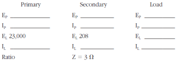
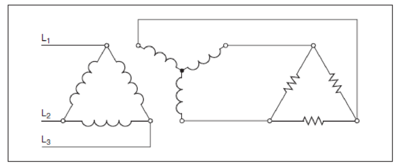
Refer to the transformer connection shown in Figure 8-31 to fill in the following values.


Figure 8-31 Practice problems circuit 2
Expert Solution & Answer
Want to see the full answer?
Check out a sample textbook solution
Students have asked these similar questions
I need expert handwritten solutions, don't use Artificial intelligence
Consider the combined gas-steam power cycle. The topping cycle is a gas-turbine cycle that has a pressure
ratio of 8. Air enters the compressor at 300 K and the turbine at 1300 K. The isentropic efficiency of the
compressor is 80%, and that of the gas turbine is 85%. The bottoming cycle is a simple Rankine cycle
operating between the pressure limits of 7 MPa and 5 kPa. Steam is heated in a heat exchanger by the
exhaust gases to a temperature of 500°C and the isentropic efficiency of the turbine is 90 %. The exhaust
gases leave the heat exchanger at 450 K. Considering the mass flow rate steam as 1 kg/s, determine:
A) Net power, B) Total input heat, C) Total entropy generation, D) Energy efficiency, E) Exergy efficiency,
F) T-s diagram
Solve by EES
Compressor
Air -③
in
Exhaust
gases
Pump
Combustion
chamber
Gas
turbine
Gas cycle
Heat exchanger
Condenser
Steam
Steam
turbine
cycle
I need expert solution s to this question, don't use Artificial intelligence
Chapter 8 Solutions
Electrical Transformers and Rotating Machines
Ch. 8 - How many transformers are needed to make an...Ch. 8 - Two transformers rated at 100 kVA each are...Ch. 8 - Prob. 3RQCh. 8 - Assume that a line voltage of 2400 volts is...Ch. 8 - Prob. 5RQCh. 8 - How much current is flowing through the secondary...Ch. 8 - How much current is flowing through the primary...Ch. 8 - Prob. 8RQCh. 8 - Prob. 9RQCh. 8 - How much current is flowing in the secondary...
Knowledge Booster
Learn more about
Need a deep-dive on the concept behind this application? Look no further. Learn more about this topic, mechanical-engineering and related others by exploring similar questions and additional content below.Similar questions
- I need solutions to this questions Don't use Artificial intelligencearrow_forwardPlease consider the following closed-loop Multiple-Input Multiple-Output (MIMO) control system: R₁(s) and R2(s) are the reference signals (or inputs), • G₁(s) (where i = 1,2,3,4,5) are the plant transfer functions, • C₁(s) and C2(s) are the responses (or system outputs), • All of them are in Laplace domain. R2 + R₁ + + G₂(s) G3(S) Tasks: G5(s) G4(s) + G₁(s) می a) Please derive the transfer function between C₁ (s) and R₂(s) (i.e., find R₂(s) (10 marks) (10 marks) b) Please derive the transfer function between C₂(s) and R₁(s) (i.e., find C2 (s)). R₁(s) Hint: Please carefully analyse how the signals interact with the plants G₁(s) and find all paths fromarrow_forwardMột thanh dài L = 2,5 m được nối bằng chốt với một con lăn ở A. Con lăn chuyển động dọc theo một đường ray nằm ngang như hình vẽ với VA 5 m/s. Xác định vận tốc của điểm C (trung điểm của thanh AB) = tại thời điểm 0 = 33° và O = 0.4 rad/s. A. v = (-5.42+0.272})(m/s) C. v = (5.421+0.272})(m/s) B. v =(0.272i+5.42j)(ms) D. (5.42-0.272)(m/s) = C Barrow_forward
- The simulink and Matlab part are the prioritized areas please.arrow_forwardPlease do not rely too much on chatgpt, because its answer may be wrong. Please consider it carefully and give your own answer. You can borrow ideas from gpt, but please do not believe its answer.Very very grateful! Please do not copy other's work,i will be very very grateful!!arrow_forwardAn industrial burner uses natural gas as fuel. The natural gas consists primarily of CH4 with small quantities of several other light hydrocarbons and can be represented as C1.16H4.32 To achieve low emissions of oxides of nitrogen, the burner operates lean at equivalence ratio of 0.4. Assume complete combustion and answer the following questions. i) What is the operating air-fuel ratio (i.e. mass air/mass of fuel)? [6 marks] ii) What is the percent excess air in the combustion products? [3 marks] iii) What is the oxygen (O2) mole fraction in the combustion products? [6 marks]arrow_forward
- 1) Consider the robot, with six degrees of freedom, RRPRR, shown in the following figure.Place the axes through the denavit-hartenberg algorithm and obtain the respective parameter table for the first three joints. 2) Considering the robot from question 1, calculate.the. Determine the Homogeneous Transformation Matrix in relation to the Direct Kinematics of the robot, for the first three joints:b. Considering the first three joints of the robot and L1 and L2 equal to 200 mm:I. calculate the pose of the robot relative to the base, knowing the joint variableshave the following values: q1= 90°, q2= 0°, q3= 50mm:arrow_forwardPlease do not rely too much on chatgpt, because its answer may be wrong. Please consider it carefully and give your own answer. You can borrow ideas from gpt, but please do not believe its answer.Very very grateful! Please do not copy other's work,i will be very very grateful!!arrow_forwardDon't use Artificial intelligencearrow_forward
arrow_back_ios
SEE MORE QUESTIONS
arrow_forward_ios
Recommended textbooks for you
 Electrical Transformers and Rotating MachinesMechanical EngineeringISBN:9781305494817Author:Stephen L. HermanPublisher:Cengage Learning
 Understanding Motor ControlsMechanical EngineeringISBN:9781337798686Author:Stephen L. HermanPublisher:Delmar Cengage Learning
 Refrigeration and Air Conditioning Technology (Mi...Mechanical EngineeringISBN:9781305578296Author:John Tomczyk, Eugene Silberstein, Bill Whitman, Bill JohnsonPublisher:Cengage Learning
 Automotive Technology: A Systems Approach (MindTa...Mechanical EngineeringISBN:9781133612315Author:Jack Erjavec, Rob ThompsonPublisher:Cengage Learning
 Automotive TechnologyMechanical EngineeringISBN:9781337794213Author:ERJAVEC, Jack.Publisher:Cengage,

Electrical Transformers and Rotating Machines
Mechanical Engineering
ISBN:9781305494817
Author:Stephen L. Herman
Publisher:Cengage Learning

Understanding Motor Controls
Mechanical Engineering
ISBN:9781337798686
Author:Stephen L. Herman
Publisher:Delmar Cengage Learning

Refrigeration and Air Conditioning Technology (Mi...
Mechanical Engineering
ISBN:9781305578296
Author:John Tomczyk, Eugene Silberstein, Bill Whitman, Bill Johnson
Publisher:Cengage Learning

Automotive Technology: A Systems Approach (MindTa...
Mechanical Engineering
ISBN:9781133612315
Author:Jack Erjavec, Rob Thompson
Publisher:Cengage Learning

Automotive Technology
Mechanical Engineering
ISBN:9781337794213
Author:ERJAVEC, Jack.
Publisher:Cengage,
Force | Free Body Diagrams | Physics | Don't Memorise; Author: Don't Memorise;https://www.youtube.com/watch?v=4Bwwq1munB0;License: Standard YouTube License, CC-BY