
Concept explainers
Videos
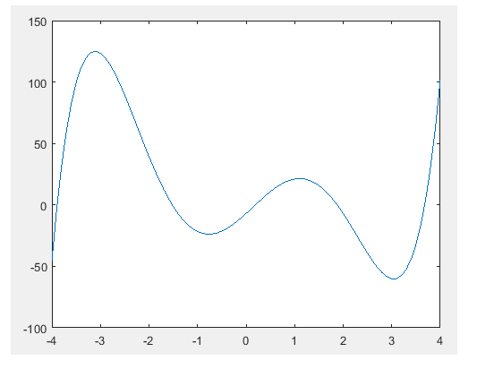
To plot:
The polynomial
Answer to Problem 1P
Solution:
The plot of the given polynomial
Explanation of Solution
The given polynomial function is,
The
Substitute the value of
Substitute the value of
Hence, the value of
Write the MATLAB script to plot the polynomial
MATLAB Code:
%MATLAB program to plot the polynomial function
x = -4:0.1:4;%Define a vector x.
y = [0.9 -0.3 -15.5 7 36 -7];
r = polyval(y,x);%polyval function is used to calculate y
plot(x,r)
Save the MATLAB script with name, Chapter8_56830_8_1P.m in the current folder. Execute the script by typing the script name at the command window to get the plot of the polynomial
Result:
Conclusion:
Therefore, the plot of the given polynomial
Want to see more full solutions like this?
Chapter 8 Solutions
EBK MATLAB: AN INTRODUCTION WITH APPLIC


- Choose the appropriate answer 1) Maximum dimension of antenna is 0.5m and operating frequency is 9 GHz, thus the radius of reactive near field region is 0.562m 1.265m 2.526m 3.265m 2) If distance between transmitter and receiver is 2km and the signal carrier frequency is 300kHz Rapidly time-varying fields DC field Quasi-static field None 3) The polarization mismatch factor for horizontal polarization wave incident on +z axis is is if the antenna polarization is circular 0.5 зав 0.707 1 4) Ez 0 and Hz #0 (HE modes): This is the case when neither E nor H field is transverse to the direction of wave propagation. They are sometimes referred to as TEM hybrid modes TM TE 5) The normalized radiation intensity of an antenna is represented by: U(6)=cos²(0) cos2 (30), w/s Half-power beamwidth HPBW is...... 28.75 10 0 14.3arrow_forwardChoose the best answer of the following: 1- quasi-static electromagnetic field is the a) low frequency b)high frequency c) time independent d) none of the above 2- Displacement current is taken to be negligible (compared to the conduction current) if a) σ>>wε b)σ << wɛ c) σ =0 d) (a and c) 3- The transmission line act as inductor when it terminated by: a) Open circuit load b) short circuit load c)matched load d)none of the above 4- The scattering aperture equals to the effective aperture when the antenna is: a) Complex conjugate matching b) short circuit c) open circuit d) none of the above 5- The isotropic point source has directivity of: a) Infinity b)1 c) 0 d)1.5arrow_forwardI selected a DC-DC converter capable of delivering 120 VDC from a 600 VDC input. When I reached out to the manufacturer, they asked for the total power consumption the converter would need to handle.To estimate this, I calculated the power requirements for the components that will use the 120 VDC supply: interior lighting, end lights, and buzzers. The breakdown is as follows:- Light Bulbs: 16 bulbs at 10 W each = 160 W- Buzzers: 2 buzzers at 5 W each = 10 W- End Lights: 2 lights at 15 W each = 30 W This results in a total estimated power demand of 200 W.My concern is whether I should request a higher wattage rating for the converter to provide sufficient tolerance and ensure the system operates efficiently without risking an overload. Note: The DC power system is designed specifically for a trolleyarrow_forward
- Choose the best answer 1. The minimum value of the directivity of an antenna is.......... a) Unity b) Zero 2. Very low signal strength in antenna. a) Minor lobes b) Null c) Infinite d) None c) Antenna patterns d) Major lobes 3. the maximum directivity of an antenna that normalized far field pattern is given by? 0≤0≤ and 0 ≤≤π/2,3л/2≤ p ≤ 2π E(0, 4) = {(sin 0 ((sin cos² ) 1/2 0 is a) 7.07dB b) 7.7dB elsewhere c) 8.7dB d) 9dB 4. the depth of penetration of 1 MHz wave in sea water which has conductivity mhos/meter and permeability approximately equal to that of free space is a) 25mm b) 25cm c)25m 5. The free space media can be considered as _ a) Lossy media b) lossless media c) good conductor 6. The input impedance is equal to the load impedance when a) l = 2 b)1=22 c)=4 d) 25km d) a and c .... d) a and barrow_forwardQ.1. choose the appropriate answer 1- When neither E nor H field is transverse to the direction of wave propagation. They are sometimes referred to as ...... a) hybrid mode b) TM mode c) TME modes d) TEM mode 2- If PLF-0 dB means......... a) Power is lost 100% b) Power is lost 0% c) Power is lost 50% d) none of the above 3. The half wave dipole is widely used in more applications compared to other linear antenna lengths, that is because..... a) It has high gain b) its easy matching to coaxial 75 Ohm cable c) low loss d) it has small size 4- The mode distribution for the end view waveguide shown below is a) TM12 b) TM21 c) TE20 end view d) TE02 5. When circular right hand polarized wave incident upon a horizontally polarized wave the PLF is a) 0 b)1 c)0.5 d)0.707arrow_forwarda- Single phase transmission line as in the figure below with the radius of the conductor is 0.5 cm, find the inductance of the total system. 4m 4m ao A B ob od 3m 6marrow_forward
- Please don't use ai to answer I will report you answerarrow_forwardA 3-phase, 4-wire distributor supplies a balanced voltage of 400/230 V to a load consisting of 8 A at p.f. 0-7 lagging for R-phase, 10 A at p.f. 0-8 leading for Y phase and 12 A at unity p.f. for B phase. The resistance of each line conductor is 0.4 2. The reactance of neutral is 0.2 2. Calculate the neutral current, the supply voltage for R phase and draw the phasor diagram. The phase sequence is RYB. IN ER VR Refarrow_forwardA 3-phase, 4-wire distributor supplies a balanced voltage of 400/230 V to a load consisting of 50 A at p.f. 0-866 lagging for R-phase, 30 A at p.f. 0-866 leading for Y phase and 30 A at unity pf. for B phase. The resistance of each line conductor is 0-2 Q. The area of X-section of neutral is half of any line conductor: Calculate the supply end voltage for R phase. The phase sequence is RYB.arrow_forward
- - A 3-phase, 4-wire distributor supplies a balanced voltage of 400/230 V to a load consisting of 8 A at p.f. 0.7 lagging for R-phase, 10 A at p.f. 0-8 leading for Y phase and 12 A at unity p.f. for B phase. The resistance of each line conductor is 0.4 2. The reactance of neutral is 0.2 2. Calculate the neutral current, the supply voltage for R phase and draw the phasor diagram. The phase sequence is RYB.arrow_forwardNo AI WILL REJECTarrow_forwardhelp on this one?arrow_forward
 Introductory Circuit Analysis (13th Edition)Electrical EngineeringISBN:9780133923605Author:Robert L. BoylestadPublisher:PEARSON
 Delmar's Standard Textbook Of ElectricityElectrical EngineeringISBN:9781337900348Author:Stephen L. HermanPublisher:Cengage Learning
 Programmable Logic ControllersElectrical EngineeringISBN:9780073373843Author:Frank D. PetruzellaPublisher:McGraw-Hill Education
 Fundamentals of Electric CircuitsElectrical EngineeringISBN:9780078028229Author:Charles K Alexander, Matthew SadikuPublisher:McGraw-Hill Education
 Electric Circuits. (11th Edition)Electrical EngineeringISBN:9780134746968Author:James W. Nilsson, Susan RiedelPublisher:PEARSON
 Engineering ElectromagneticsElectrical EngineeringISBN:9780078028151Author:Hayt, William H. (william Hart), Jr, BUCK, John A.Publisher:Mcgraw-hill Education,