
Statics and Mechanics of Materials Plus Mastering Engineering with Pearson eText - Access Card Package (5th Edition)
5th Edition
ISBN: 9780134301006
Author: Russell C. Hibbeler
Publisher: PEARSON
expand_more
expand_more
format_list_bulleted
Concept explainers
Videos
Textbook Question
Chapter 7.6, Problem 55P
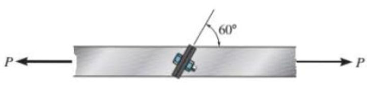
The tension member is fastened together using two bolts, one on each side of the member as shown. Each bolt has a diameter of 0.3 in. Determine the maximum load P that can be applied to the member if the allowable shear stress for the bolts is τallow = 12 ksi and the allowable average normal stress is σallow = 20 ksi.
Prob. 7–55
Expert Solution & Answer
Want to see the full answer?
Check out a sample textbook solution
Students have asked these similar questions
The force F1 = 10 kN, F2 = 10 kN, F3 = 10 kN, F4 = 5
KN are acting on the sttructure shown. Determine the forces
in the members specified below. Use positive values to
indicate tension and negative values to indicate compression.
F2
D
b
F1
F3 C
E
b
F4
b
B
F
a
G
Values for dimensions on the figure are given in the following
table. Note the figure may not be to scale.
Variable Value
a
3 m
b
4 m
The force in member BC is
KN.
The force in member BE is
KN.
The force in member EF is
KN.
h
=
The transmission tower is subjected to the forces F₁ 3.6
KN at 50° and F2 = 3.3 kN at = 35°. Determine the
forces in members BC, BP, PQ, PC, CD, DP and NP.
Use positive values to indicate tension and negative values to
indicate compression.
不
кажаж в *а*аж
E
N
M
d
d
IF, c
B
CENTER
LINE
S
อ
K
F₂
Kbb
cc 10
BY NC SA
2013 Michael Swanbom
Values for dimensions on the figure are given in the following
table. Note the figure may not be to scale.
Variable
Value
a
1.7 m
b
4.9 m
с
3 m
d
5.2 m
h
8.4 m
Values for dimensions on the figure are given in the following
table. Note the figure may not be to scale.
Variable Value
a
1.7 m
4.9 m
с
3 m
d
5.2 m
h
8.4 m
The force in member BC is
KN.
The force in member BP is
KN.
The force in member PQ is
KN.
The force in member PC is
KN.
The force in member CD is
KN.
The force in member DP is
KN.
The force in member NP is
KN.
نصاف
Sheet
Asteel bar of rectangular cross section with
dimension
Shown in fig. below. This bar is
as
Connected toawell. Using welded Join a long the sides
als only find the weld size (h). Where:
Tall = 35 MN/M²
F=213.30
answer/h=
4.04
☐
Yomm
Soomm
100mm
Chapter 7 Solutions
Statics and Mechanics of Materials Plus Mastering Engineering with Pearson eText - Access Card Package (5th Edition)
Ch. 7.2 - In each case, explain how to find the resultant...Ch. 7.2 - Determine the internal normal force, shear force,...Ch. 7.2 - Determine the internal normal force, shear force,...Ch. 7.2 - Determine the internal normal force, shear force,...Ch. 7.2 - Determine the internal normal force, shear force,...Ch. 7.2 - Determine the internal normal force, shear force,...Ch. 7.2 - Determine the internal normal force, shear force,...Ch. 7.2 - The shaft is supported by a smooth thrust bearing...Ch. 7.2 - Determine the resultant internal normal and shear...Ch. 7.2 - Determine the resultant internal loadings acting...
Ch. 7.2 - The shaft is supported by a smooth thrust bearing...Ch. 7.2 - Determine the resultant internal loadings acting...Ch. 7.2 - Determine the resultant internal loadings on the...Ch. 7.2 - Determine the resultant internal loadings at cross...Ch. 7.2 - Prob. 8PCh. 7.2 - The beam supports the distributed load shown....Ch. 7.2 - The boom DF of the jib crane and the column DE...Ch. 7.2 - Determine the resultant internal loadings acting...Ch. 7.2 - Determine the resultant internal loadings acting...Ch. 7.2 - The blade of the hacksaw is subjected to a...Ch. 7.2 - The blade of the hacksaw is subjected to a...Ch. 7.2 - The beam supports the triangular distributed load...Ch. 7.2 - The beam supports the distributed load shown....Ch. 7.2 - The shaft is supported at its ends by two bearings...Ch. 7.2 - The shaft is supported at its ends by two bearings...Ch. 7.2 - The hand crank that is used in a press has the...Ch. 7.2 - Determine the resultant internal loadings acting...Ch. 7.2 - Determine the resultant internal loadings acting...Ch. 7.2 - The metal stud punch is subjected to a force of...Ch. 7.2 - Determine the resultant internal loadings acting...Ch. 7.2 - Prob. 24PCh. 7.2 - Determine the resultant internal loadings acting...Ch. 7.5 - In each case, determine the largest internal shear...Ch. 7.5 - Determine the largest internal normal force in the...Ch. 7.5 - Determine the internal normal force at section A...Ch. 7.5 - The lever is held to the fixed shaft using the pin...Ch. 7.5 - Prob. 6PPCh. 7.5 - Prob. 7FPCh. 7.5 - Determine the average normal stress on the cross...Ch. 7.5 - Prob. 9FPCh. 7.5 - If the 600-kN force acts through the centroid of...Ch. 7.5 - Prob. 11FPCh. 7.5 - Prob. 12FPCh. 7.5 - The supporting wheel on a scaffold is held in...Ch. 7.5 - Determine the largest intensity w of the uniform...Ch. 7.5 - Prob. 28PCh. 7.5 - The small block has a thickness of 0.5 in. If the...Ch. 7.5 - Prob. 30PCh. 7.5 - If the block is subjected to a centrally applied...Ch. 7.5 - Prob. 32PCh. 7.5 - The board is subjected to a tensile force of 200...Ch. 7.5 - The boom has a uniform weight of 600 lb and is...Ch. 7.5 - Determine the average normal stress in each of the...Ch. 7.5 - If the average normal stress in each of the...Ch. 7.5 - Determine the maximum average shear stress in pin...Ch. 7.5 - Prob. 38PCh. 7.5 - Prob. 39PCh. 7.5 - The column is made of concrete having a density of...Ch. 7.5 - The beam is supported by two rods AB and CD that...Ch. 7.5 - The beam is supported by two rods AB and CD that...Ch. 7.5 - Prob. 43PCh. 7.5 - The railcar docklight is supported by the...Ch. 7.5 - The plastic block is subjected to an axial...Ch. 7.5 - The two steel members are joined together using a...Ch. 7.5 - The bar has a cross-sectional area of 400(106) m2....Ch. 7.5 - Prob. 48PCh. 7.5 - The two members used in the construction of an...Ch. 7.5 - Prob. 50PCh. 7.5 - Prob. 51PCh. 7.6 - Rods AC and BC are used to suspend the 200-kg...Ch. 7.6 - The pin at A has a diameter of 0.25 in. If it is...Ch. 7.6 - Prob. 15FPCh. 7.6 - Prob. 16FPCh. 7.6 - The strut is glued to the horizontal member at...Ch. 7.6 - Prob. 18FPCh. 7.6 - Prob. 19FPCh. 7.6 - Prob. 20FPCh. 7.6 - Prob. 21FPCh. 7.6 - The pin is made of a material having a failure...Ch. 7.6 - Prob. 23FPCh. 7.6 - Prob. 24FPCh. 7.6 - Prob. 52PCh. 7.6 - Prob. 53PCh. 7.6 - The connection is made using a bolt and nut and...Ch. 7.6 - The tension member is fastened together using two...Ch. 7.6 - Prob. 56PCh. 7.6 - Prob. 57PCh. 7.6 - Determine the size of square bearing plates A and...Ch. 7.6 - Determine the maximum load P that can be applied...Ch. 7.6 - Determine the required diameter of the pins at A...Ch. 7.6 - Prob. 61PCh. 7.6 - Prob. 62PCh. 7.6 - The cotter is used to hold the two rods together...Ch. 7.6 - Determine the required diameter of the pins at A...Ch. 7.6 - The steel pipe is supported on the circular base...Ch. 7.6 - Prob. 66PCh. 7.6 - The boom is supported by the winch cable that has...Ch. 7.6 - The assembly consists of three disks A, B, and C...Ch. 7.6 - Prob. 69PCh. 7.6 - The two aluminum rods AB and AC have diameters of...Ch. 7.8 - A loading causes the member to deform into the...Ch. 7.8 - Prob. 8PPCh. 7.8 - A loading causes the wires to elongate into the...Ch. 7.8 - Prob. 10PPCh. 7.8 - Prob. 11PPCh. 7.8 - Prob. 25FPCh. 7.8 - If the force P causes the rigid arm ABC to rotate...Ch. 7.8 - The rectangular plate is deformed into the shape...Ch. 7.8 - The triangular plate is deformed into the shape...Ch. 7.8 - The square plate is deformed into the shape shown...Ch. 7.8 - Prob. 71PCh. 7.8 - Prob. 72PCh. 7.8 - If the load P on the beam causes the end C to be...Ch. 7.8 - The force applied at the handle of the rigid lever...Ch. 7.8 - The rectangular plate is subjected to the...Ch. 7.8 - Prob. 76PCh. 7.8 - Prob. 77PCh. 7.8 - Prob. 78PCh. 7.8 - Prob. 79PCh. 7.8 - Prob. 80PCh. 7.8 - Determine the shear strain xy at corners D and C...Ch. 7.8 - The material distorts into the dashed position...Ch. 7.8 - Prob. 83PCh. 7.8 - Determine the shear strain xy at comers A and B if...Ch. 7.8 - Prob. 85PCh. 7.8 - Determine the average normal strain that occurs...Ch. 7.8 - The corners of the square plate are given the...Ch. 7.8 - Prob. 88PCh. 7.8 - Prob. 89PCh. 7.8 - The triangular plate is fixed at its base, and its...Ch. 7.8 - The polysulfone block is glued at its top and...Ch. 7 - The beam AB is pin supported at A and supported by...Ch. 7 - The long bolt passes through the 30-mm-thick...Ch. 7 - Determine the required thickness of member BC and...Ch. 7 - The circular punch B exerts a force of 2 kN on the...Ch. 7 - Prob. 5RPCh. 7 - Prob. 6RPCh. 7 - The square plate is deformed into the shape shown...Ch. 7 - Prob. 8RPCh. 7 - The rubber block is fixed along edge AB, and edge...
Knowledge Booster


Learn more about
Need a deep-dive on the concept behind this application? Look no further. Learn more about this topic, mechanical-engineering and related others by exploring similar questions and additional content below.Similar questions
- True and False Indicate if each statement is true or false. T/F 1. Rule #1 protects the function of assembly. T/F 2. One of the fundamental dimensioning rules requires all dimensions apply in the free-state condition for rigid parts. T/F 3. The fundamental dimensioning rules that apply on a drawing must be listed in the general notes. T/F 4. Where Rule #1 applies to a drawing, it limits the form of every feature of size on the drawing. T/F 5. Rule #1 limits the variation between features of size on a part. T/F 6. The designer must specify on the drawing which features of size use Rule #1. T/F T/F T/F 7. Rule #1 applies to nonrigid parts (in the unrestrained state). 8. A GO gage is a fixed-limit gage. 9. Rule #1 requires that the form of an individual regular feature of size is controlled by its limits of sizearrow_forwardFEAarrow_forwardFEAarrow_forward
- FEAarrow_forwardنصاف Sheet Asteel bar of rectangular cross section with dimension Shown in fig. below. This bar is as Connected toawell. Using welded Join a long the sides als only find the weld size (h). Where: Tall = 35 MN/M² F=213.30 answer/h= 4.04 ☐ Yomm Soomm 100mmarrow_forwardPlease also draw the FBDsarrow_forward
arrow_back_ios
SEE MORE QUESTIONS
arrow_forward_ios
Recommended textbooks for you
 Elements Of ElectromagneticsMechanical EngineeringISBN:9780190698614Author:Sadiku, Matthew N. O.Publisher:Oxford University Press
 Mechanics of Materials (10th Edition)Mechanical EngineeringISBN:9780134319650Author:Russell C. HibbelerPublisher:PEARSON
 Thermodynamics: An Engineering ApproachMechanical EngineeringISBN:9781259822674Author:Yunus A. Cengel Dr., Michael A. BolesPublisher:McGraw-Hill Education
 Control Systems EngineeringMechanical EngineeringISBN:9781118170519Author:Norman S. NisePublisher:WILEY
 Mechanics of Materials (MindTap Course List)Mechanical EngineeringISBN:9781337093347Author:Barry J. Goodno, James M. GerePublisher:Cengage Learning
 Engineering Mechanics: StaticsMechanical EngineeringISBN:9781118807330Author:James L. Meriam, L. G. Kraige, J. N. BoltonPublisher:WILEY
Elements Of Electromagnetics
Mechanical Engineering
ISBN:9780190698614
Author:Sadiku, Matthew N. O.
Publisher:Oxford University Press
Mechanics of Materials (10th Edition)
Mechanical Engineering
ISBN:9780134319650
Author:Russell C. Hibbeler
Publisher:PEARSON
Thermodynamics: An Engineering Approach
Mechanical Engineering
ISBN:9781259822674
Author:Yunus A. Cengel Dr., Michael A. Boles
Publisher:McGraw-Hill Education
Control Systems Engineering
Mechanical Engineering
ISBN:9781118170519
Author:Norman S. Nise
Publisher:WILEY
Mechanics of Materials (MindTap Course List)
Mechanical Engineering
ISBN:9781337093347
Author:Barry J. Goodno, James M. Gere
Publisher:Cengage Learning
Engineering Mechanics: Statics
Mechanical Engineering
ISBN:9781118807330
Author:James L. Meriam, L. G. Kraige, J. N. Bolton
Publisher:WILEY
Pressure Vessels Introduction; Author: Engineering and Design Solutions;https://www.youtube.com/watch?v=Z1J97IpFc2k;License: Standard youtube license