
Engineering Mechanics: Statics and Study Pack (13th Edition)
13th Edition
ISBN: 9780133027990
Author: Russell C. Hibbeler
Publisher: Prentice Hall
expand_more
expand_more
format_list_bulleted
Concept explainers
Videos
Textbook Question
Chapter 7.4, Problem 133RP
Draw the shear and moment diagrams for the beam.
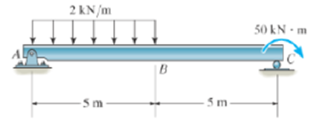
Prob. R7-5
Expert Solution & Answer
Want to see the full answer?
Check out a sample textbook solution
Students have asked these similar questions
answer this as soon as possible, please.
A piston–cylinder device contains 50 kg of water at 250 kPa and 25°C. The cross-sectional area of the piston is 0.1 m2. Heat is now transferred to the water, causing part of it to evaporate and expand. When the volume reaches 0.26 m3, the piston reaches a linear spring whose spring constant is 100 kN/m. More heat is transferred to the water until the piston rises 20 cm more.
NOTE: This is a multi-part question. Once an answer is submitted, you will be unable to return to this part.
Determine the work done during this process.
The work done during this process is kJ.
A 4-m × 5-m × 7-m room is heated by the radiator of a steam-heating system. The steam radiator transfers heat at a rate of 10,000 kJ/h, and a 100-W fan is used to distribute the warm air in the room. The rate of heat loss from the room is estimated to be about 5000 kJ/h. If the initial temperature of the room air is 10°C, determine how long it will take for the air temperature to rise to 25°C. Assume constant specific heats at room temperature. The gas constant of air is R = 0.287 kPa·m3/kg·K (Table A-1). Also, cv = 0.718 kJ/kg·K for air at room temperature (Table A-2).
Steam enters the radiator system through an inlet outside the room and leaves the system through an outlet on the same side of the room. The fan is labeled as W sub p w. The heat is given off by the whole system consisting of room, radiator and fan at the rate of 5000 kilojoules per hour.
It will take 831 Numeric ResponseEdit Unavailable. 831 incorrect.s for the air temperature to rise to 25°C.
Chapter 7 Solutions
Engineering Mechanics: Statics and Study Pack (13th Edition)
Ch. 7.1 - Determine the normal force, shear force, and...Ch. 7.1 - Determine the normal force, shear force, and...Ch. 7.1 - Determine the normal force, shear force, and...Ch. 7.1 - Determine the normal force, shear force, and...Ch. 7.1 - Determine the normal force, shear force, and...Ch. 7.1 - Assume A is pinned and B is a roller. Prob. F7-6Ch. 7.1 - Assume the support at B is a roller. Point C is...Ch. 7.1 - Determine the shear force and moment at points C...Ch. 7.1 - If the suspended load has a weight of 2 kN and a...Ch. 7.1 - Prob. 4P
Ch. 7.1 - Prob. 5PCh. 7.1 - Determine the distance a as a fraction of the...Ch. 7.1 - Prob. 7PCh. 7.1 - Prob. 8PCh. 7.1 - Take P = 8 kN. Prob. 7-9Ch. 7.1 - Determine the largest vertical load P the frame...Ch. 7.1 - The shaft is supported by a journal bearing at A...Ch. 7.1 - Determine the internal normal force, shear force,...Ch. 7.1 - Prob. 13PCh. 7.1 - Prob. 14PCh. 7.1 - Prob. 15PCh. 7.1 - Prob. 16PCh. 7.1 - Prob. 17PCh. 7.1 - Point E is just to the right of the 3-kip load....Ch. 7.1 - Prob. 19PCh. 7.1 - Determine the internal normal force, shear force,...Ch. 7.1 - Prob. 21PCh. 7.1 - Prob. 22PCh. 7.1 - Prob. 23PCh. 7.1 - Determine the internal normal force, shear force,...Ch. 7.1 - Prob. 25PCh. 7.1 - Determine the ratio of a/b for which the shear...Ch. 7.1 - Prob. 27PCh. 7.1 - Prob. 28PCh. 7.1 - Determine the normal force, shear force, and...Ch. 7.1 - Determine the normal force, shear force, and...Ch. 7.1 - Prob. 31PCh. 7.1 - Prob. 32PCh. 7.1 - Prob. 33PCh. 7.1 - Prob. 34PCh. 7.1 - Prob. 35PCh. 7.1 - Prob. 36PCh. 7.1 - Prob. 37PCh. 7.1 - Prob. 38PCh. 7.1 - Prob. 39PCh. 7.1 - Prob. 40PCh. 7.1 - Determine the x, y, z components of force and...Ch. 7.1 - z components of force and moment at point C in the...Ch. 7.1 - Prob. 43PCh. 7.1 - Prob. 44PCh. 7.2 - Determine the shear and moment as a function of x,...Ch. 7.2 - Determine the shear and moment as a function of x,...Ch. 7.2 - Determine the shear and moment as a function of x,...Ch. 7.2 - Determine the shear and moment as a function of x,...Ch. 7.2 - Determine the shear and moment as a function of x,...Ch. 7.2 - Determine the shear and moment as a function of x,...Ch. 7.2 - Prob. 45PCh. 7.2 - Draw the shear and moment diagrams for the beam...Ch. 7.2 - Draw the shear and moment diagrams for the beam...Ch. 7.2 - Draw the shear and moment diagrams of the beam (a)...Ch. 7.2 - If L = 9 m, the beam will fail when the maximum...Ch. 7.2 - Draw the shear and moment diagrams for the...Ch. 7.2 - Prob. 51PCh. 7.2 - Prob. 52PCh. 7.2 - Draw the shear and moment diagrams for the beam....Ch. 7.2 - Prob. 54PCh. 7.2 - Draw the shear and bending-moment diagrams for the...Ch. 7.2 - Prob. 56PCh. 7.2 - Draw the shear and bending-moment diagrams for...Ch. 7.2 - Draw the shear and moment diagrams for the...Ch. 7.2 - Prob. 59PCh. 7.2 - The shaft is supported by a smooth thrust bearing...Ch. 7.2 - Prob. 61PCh. 7.2 - Prob. 62PCh. 7.2 - Prob. 63PCh. 7.2 - Prob. 64PCh. 7.2 - Prob. 65PCh. 7.2 - Draw the shear and moment diagrams for the beam....Ch. 7.2 - Prob. 67PCh. 7.2 - Prob. 68PCh. 7.2 - Express the internal shear and moment components...Ch. 7.3 - Draw the shear and moment diagrams for the beam....Ch. 7.3 - Draw the shear and moment diagrams for the beam....Ch. 7.3 - Draw the shear and moment diagrams for the beam....Ch. 7.3 - Draw the shear and moment diagrams for the beam....Ch. 7.3 - Draw the shear and moment diagrams for the beam....Ch. 7.3 - Draw the shear and moment diagrams for the beam....Ch. 7.3 - Prob. 70PCh. 7.3 - Prob. 71PCh. 7.3 - Draw the shear and moment diagrams for the beam....Ch. 7.3 - Prob. 73PCh. 7.3 - Draw the shear and moment diagrams for the...Ch. 7.3 - Draw the shear and moment diagrams for the beam....Ch. 7.3 - Prob. 76PCh. 7.3 - Prob. 77PCh. 7.3 - Draw the shear and moment diagrams for the shaft....Ch. 7.3 - Draw the shear and moment diagrams for the beam....Ch. 7.3 - Prob. 80PCh. 7.3 - Prob. 81PCh. 7.3 - Prob. 82PCh. 7.3 - Prob. 83PCh. 7.3 - Prob. 84PCh. 7.3 - Prob. 85PCh. 7.3 - Prob. 86PCh. 7.3 - Prob. 87PCh. 7.3 - Prob. 88PCh. 7.3 - Prob. 89PCh. 7.3 - Prob. 90PCh. 7.3 - Prob. 91PCh. 7.3 - Prob. 92PCh. 7.3 - Prob. 93PCh. 7.4 - Prob. 94PCh. 7.4 - Prob. 95PCh. 7.4 - Determine the tension in each segment of the cable...Ch. 7.4 - Prob. 97PCh. 7.4 - Prob. 98PCh. 7.4 - Prob. 99PCh. 7.4 - If cylinder E has a mass of 20 kg and each cable...Ch. 7.4 - Prob. 101PCh. 7.4 - Prob. 102PCh. 7.4 - If yB = 1.5 ft. determine the largest weight of...Ch. 7.4 - The cable AB is subjected to a uniform loading of...Ch. 7.4 - Determine the maximum uniform loading w, measured...Ch. 7.4 - The cable is subjected to a uniform loading of w =...Ch. 7.4 - Prob. 107PCh. 7.4 - Prob. 108PCh. 7.4 - If the pipe has a mass per unit length of 1500...Ch. 7.4 - Prob. 110PCh. 7.4 - Prob. 111PCh. 7.4 - Prob. 112PCh. 7.4 - Prob. 113PCh. 7.4 - A telephone line (cable) stretches between two...Ch. 7.4 - Prob. 115PCh. 7.4 - Prob. 116PCh. 7.4 - Prob. 117PCh. 7.4 - A cable has a weight of 5 lb/ft. If it can span...Ch. 7.4 - Prob. 119PCh. 7.4 - The power transmission cable weighs 10 lb/fl. If...Ch. 7.4 - The power transmission cable weighs 10 lb/ft. If h...Ch. 7.4 - Prob. 122PCh. 7.4 - Prob. 123PCh. 7.4 - The man picks up the 52-ft chain and holds it just...Ch. 7.4 - Determine the internal normal force, shear force,...Ch. 7.4 - Draw the shear and moment diagrams for the beam....Ch. 7.4 - Prob. 127RPCh. 7.4 - Prob. 128RPCh. 7.4 - Prob. 129RPCh. 7.4 - Prob. 130RPCh. 7.4 - Prob. 131RPCh. 7.4 - Prob. 132RPCh. 7.4 - Draw the shear and moment diagrams for the beam....Ch. 7.4 - Determine the normal force, shear force, and...Ch. 7.4 - Draw the shear and moment diagrams for the beam....Ch. 7.4 - Prob. 137RPCh. 7.4 - Prob. 138RPCh. 7.4 - Prob. 139RP
Knowledge Booster


Learn more about
Need a deep-dive on the concept behind this application? Look no further. Learn more about this topic, mechanical-engineering and related others by exploring similar questions and additional content below.Similar questions
- A piston–cylinder device contains 50 kg of water at 250 kPa and 25°C. The cross-sectional area of the piston is 0.1 m2. Heat is now transferred to the water, causing part of it to evaporate and expand. When the volume reaches 0.26 m3, the piston reaches a linear spring whose spring constant is 100 kN/m. More heat is transferred to the water until the piston rises 20 cm more. NOTE: This is a multi-part question. Once an answer is submitted, you will be unable to return to this part. Determine the final pressure and temperature. The final pressure is kPa. The final temperature is ºC. Find the work done during the processarrow_forwardA garden hose attached with a nozzle is used to fill a 20-gal bucket. The inner diameter of the hose is 1 in and it reduces to 0.53 in at the nozzle exit. The average velocity in the hose is 8 ft/s and the density of water is 62.4 lbm/ft3. NOTE: This is a multi-part question. Once an answer is submitted, you will be unable to return to this part. Determine the volume and mass flow rates of water through the hose. The volume flow rate of water through the hose is ft3/s. The mass flow rate of water through the hose is lbm/s. The change in time? What is the exit velocity?arrow_forwardA 23-ft3 rigid tank initially contains saturated refrigerant-134a vapor at 160 psia. As a result of heat transfer from the refrigerant, the pressure drops to 50 psia. NOTE: This is a multi-part question. Once an answer is submitted, you will be unable to return to this part. Determine the final temperature. Use data from refrigerant tables. The final temperature is ºF.arrow_forward
- A 23-ft3 rigid tank initially contains saturated refrigerant-134a vapor at 160 psia. As a result of heat transfer from the refrigerant, the pressure drops to 50 psia. NOTE: This is a multi-part question. Once an answer is submitted, you will be unable to return to this part. Determine the heat transfer. The heat transfer is Btu.arrow_forwardThe shaft shown in the figure below is subjected to axial loads as illustrated. The diameters of segments AB, BC, and CD are 20mm, 25mm, and 15mm, respectively. If the modulus of elasticity of the material is 610 MPa. Determine the change of A to D lengtharrow_forwardDetermine the final pressure and temperature. The final pressure is kPa. The final temperature is ºC.arrow_forward
- Air enters the 1-m2 inlet of an aircraft engine at 100 kPa and 20°C with a velocity of 184 m/s. Determine the volume flow rate, in m3/s, at the engine’s inlet and the mass flow rate, in kg/s, at the engine’s exit. The gas constant of air is R = 0.287 kPa·m3/kg·K. The volume flow rate at the engine’s inlet m3/s. The mass flow rate at the engine’s exit is kg/s.arrow_forwardThe ventilating fan of the bathroom of a building has a volume flow rate of 33 L/s and runs continuously. If the density of air inside is 1.20 kg/m3, determine the mass of air vented out in one day. The mass of air is kg.arrow_forwardA steady-flow compressor is used to compress helium from 15 psia and 70°F at the inlet to 200 psia and 600°F at the outlet. The outlet area and velocity are 0.01 ft2 and 100 ft/s, respectively, and the inlet velocity is 53 ft/s. Determine the mass flow rate and the inlet area. The gas constant of helium is R = 2.6809 psia·ft3/lbm·R. The mass flow rate is lbm/s. The inlet area is ft2.arrow_forward
- 1. The maximum and minimum stresses as well as the shear stress seen subjected the piece in plane A-A. Assume it is a cylinder with a diameter of 12.7mm 2. Draw the Mohr circle for the stress state using software. 3. Selection of the material for the prosthesis, which must be analyzed from the point of safety and cost view.arrow_forwardMarrow_forward× Your answer is incorrect. (Manometer) Determine the angle 0 of the inclined tube shown in figure below if the pressure at A is 1 psi greater than that at B. 1ft SG=0.61 十 A Ꮎ 1ft SG=1.0 8.8 ft 0 = Hi 15.20 deg Airarrow_forward
arrow_back_ios
SEE MORE QUESTIONS
arrow_forward_ios
Recommended textbooks for you
 Elements Of ElectromagneticsMechanical EngineeringISBN:9780190698614Author:Sadiku, Matthew N. O.Publisher:Oxford University Press
 Mechanics of Materials (10th Edition)Mechanical EngineeringISBN:9780134319650Author:Russell C. HibbelerPublisher:PEARSON
 Thermodynamics: An Engineering ApproachMechanical EngineeringISBN:9781259822674Author:Yunus A. Cengel Dr., Michael A. BolesPublisher:McGraw-Hill Education
 Control Systems EngineeringMechanical EngineeringISBN:9781118170519Author:Norman S. NisePublisher:WILEY
 Mechanics of Materials (MindTap Course List)Mechanical EngineeringISBN:9781337093347Author:Barry J. Goodno, James M. GerePublisher:Cengage Learning
 Engineering Mechanics: StaticsMechanical EngineeringISBN:9781118807330Author:James L. Meriam, L. G. Kraige, J. N. BoltonPublisher:WILEY
Elements Of Electromagnetics
Mechanical Engineering
ISBN:9780190698614
Author:Sadiku, Matthew N. O.
Publisher:Oxford University Press
Mechanics of Materials (10th Edition)
Mechanical Engineering
ISBN:9780134319650
Author:Russell C. Hibbeler
Publisher:PEARSON
Thermodynamics: An Engineering Approach
Mechanical Engineering
ISBN:9781259822674
Author:Yunus A. Cengel Dr., Michael A. Boles
Publisher:McGraw-Hill Education
Control Systems Engineering
Mechanical Engineering
ISBN:9781118170519
Author:Norman S. Nise
Publisher:WILEY
Mechanics of Materials (MindTap Course List)
Mechanical Engineering
ISBN:9781337093347
Author:Barry J. Goodno, James M. Gere
Publisher:Cengage Learning
Engineering Mechanics: Statics
Mechanical Engineering
ISBN:9781118807330
Author:James L. Meriam, L. G. Kraige, J. N. Bolton
Publisher:WILEY
Understanding Shear Force and Bending Moment Diagrams; Author: The Efficient Engineer;https://www.youtube.com/watch?v=C-FEVzI8oe8;License: Standard YouTube License, CC-BY
Bending Stress; Author: moodlemech;https://www.youtube.com/watch?v=9QIqewkE6xM;License: Standard Youtube License