Mechanics of Materials, Student Value Edition Plus Mastering Engineering with Pearson eText -- Access Card Package (10th Edition)
10th Edition
ISBN: 9780134326054
Author: Russell C. Hibbeler
Publisher: PEARSON
expand_more
expand_more
format_list_bulleted
Concept explainers
Videos
Textbook Question
Chapter 7.2, Problem 7.3FP
Determine the absolute maximum shear stress in the beam.
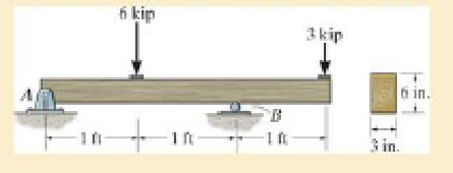
F7–3
Expert Solution & Answer
Want to see the full answer?
Check out a sample textbook solution
Students have asked these similar questions
The thin-walled open cross section shown is transmitting torque 7. The angle of twist ₁ per unit length of each leg can be
determined separately using the equation
01
=
3Ti
GLIC
3
where G is the shear modulus, ₁ is the angle of twist per unit length, T is torque, and L is the length of the median line.
In this case, i = 1, 2, 3, and T; represents the torque in leg i. Assuming that the angle of twist per unit length for each
leg is the same, show that
T= Lic³ and Tmaz = G01 Cmax
Consider a steel section with Tallow = 12.40 kpsi.
C1
2 mm
L1
20 mm
C2
3 mm
L2
30 mm
C3
2 mm
L3
25 mm
Determine the torque transmitted by each leg and the torque transmitted by the entire section.
The torque transmitted by the first leg is |
N-m.
The torque transmitted by the second leg is
N-m.
The torque transmitted by the third leg is
N-m.
The torque transmitted by the entire section is
N-m.
Please help, make sure it's to box out and make it clear what answers go where...
The cylinder floats in the water and oil to the level shown. Determine the weight of the cylinder. (rho)o=910 kg/m^3
Chapter 7 Solutions
Mechanics of Materials, Student Value Edition Plus Mastering Engineering with Pearson eText -- Access Card Package (10th Edition)
Ch. 7.2 - In each case, calculate the value of Q and t that...Ch. 7.2 - If the beam is subjected to a shear force of V =...Ch. 7.2 - Determine the shear stress at points A and B if...Ch. 7.2 - Determine the absolute maximum shear stress in the...Ch. 7.2 - If the beam is subjected to a shear force of V =20...Ch. 7.2 - If the beam is made from four plates and subjected...Ch. 7.2 - If the wide-flange beam is subjected to a shear of...Ch. 7.2 - If the wide-flange beam is subjected to a shear of...Ch. 7.2 - If the wide-flange beam is subjected to a shear of...Ch. 7.2 - If the beam is subjected to a shear of V = 30 kN,...
Ch. 7.2 - If the wide-flange beam is subjected to a shear of...Ch. 7.2 - The wood beam has an allowable shear stress of...Ch. 7.2 - The shaft is supported by a thrust bearing at A...Ch. 7.2 - The shaft is supported by a thrust bearing at A...Ch. 7.2 - Determine the largest shear force V that the...Ch. 7.2 - If the applied shear force V = 18 kip, determine...Ch. 7.2 - The overhang beam is subjected to the uniform...Ch. 7.2 - The beam is made from a polymer and is subjected...Ch. 7.2 - Determine the maximum shear stress in the strut if...Ch. 7.2 - Determine the maximum shear force V that the strut...Ch. 7.2 - Sketch the intensity of the shear-stress...Ch. 7.2 - Plot the shear-stress distribution over the cross...Ch. 7.2 - If the beam is subjected to a shear of V=15 kN,...Ch. 7.2 - If the wide-flange beam is subjected to a shear of...Ch. 7.2 - If the wide-flange beam is subjected to a shear of...Ch. 7.2 - Determine the length of the cantilevered beam so...Ch. 7.2 - If the beam is made from wood having an allowable...Ch. 7.2 - Determine the largest intensity w of the...Ch. 7.2 - If w=800 lb/ft, determine the absolute maximum...Ch. 7.2 - Determine the shear stress at point B on the web...Ch. 7.2 - Determine the maximum shear stress acting at...Ch. 7.2 - Railroad ties must be designed to resist large...Ch. 7.2 - The beam is slit longitudinally along both sides....Ch. 7.2 - The beam is to be cut longitudinally along both...Ch. 7.2 - The composite beam is constructed from wood and...Ch. 7.2 - The beam has a rectangular cross section and is...Ch. 7.2 - The beam in Fig.6-48f is subjected to a fully...Ch. 7.3 - The two identical boards are bolted together to...Ch. 7.3 - Two identical 20-mm-thick plates are bolted to the...Ch. 7.3 - The boards are bolted together to form the...Ch. 7.3 - The boards are bolted together to form the...Ch. 7.3 - The beam is constructed from two boards fastened...Ch. 7.3 - The beam is constructed from two boards fastened...Ch. 7.3 - The beam is constructed from three boards. If it...Ch. 7.3 - The beam is constructed from three boards....Ch. 7.3 - The double T-beam is fabricated by welding the...Ch. 7.3 - The double T-beam is fabricated by welding the...Ch. 7.3 - The beam is constructed from three boards....Ch. 7.3 - A beam is constructed from three boards bolted...Ch. 7.3 - The simply supported beam is built up from three...Ch. 7.3 - The simply supported beam is built up from three...Ch. 7.3 - The T-beam is constructed as shown. If each nail...Ch. 7.3 - The box beam is constructed from four boards that...Ch. 7.3 - The box beam is constructed from four boards that...Ch. 7.3 - The member consists of two plastic channel strips...Ch. 7.3 - The member consists of two plastic channel strips...Ch. 7.3 - The beam is made from four boards nailed together...Ch. 7.3 - The beam is made from three polystyrene strips...Ch. 7.5 - A shear force of V=300 kN is applied to the box...Ch. 7.5 - A shear force of V=450 kN is applied to the box...Ch. 7.5 - A shear force of V = 18 kN is applied to the box...Ch. 7.5 - A shear force of V = 18 kN is applied to the box...Ch. 7.5 - The aluminum strut is 10 mm thick and has the...Ch. 7.5 - The aluminum strut is 10 mm thick and has the...Ch. 7.5 - The beam is subjected to a shear force of V=50...Ch. 7.5 - The beam is subjected to a shear force of V=50...Ch. 7.5 - The H-beam is subjected to a shear of V=80 kN...Ch. 7.5 - The H-beam is subjected to a shear of V=80 kN...Ch. 7.5 - The built-up beam is formed by welding together...Ch. 7.5 - The assembly is subjected to a vertical shear of V...Ch. 7.5 - The box girder is subjected to a shear of V=15 kN....Ch. 7.5 - Determine the location e of the shear center,...Ch. 7.5 - Determine the location e of the shear center,...Ch. 7.5 - The beam supports a vertical shear of V=7 kip....Ch. 7.5 - The stiffened beam is constructed from plates...Ch. 7.5 - The pipe is subjected to a shear force of V=8 kip....Ch. 7.5 - Determine the location e of the shear center,...Ch. 7.5 - A thin plate of thickness t is bent to form the...Ch. 7.5 - Determine the location e of the shear center,...Ch. 7 - The beam is fabricated from four boards nailed...Ch. 7 - The T-beam is subjected to a shear of V = 150 kN....Ch. 7 - The member is subject to a shear force of V = 2...Ch. 7 - Determine the shear stress at points B and C on...Ch. 7 - Determine the maximum shear stress acting at...
Knowledge Booster


Learn more about
Need a deep-dive on the concept behind this application? Look no further. Learn more about this topic, mechanical-engineering and related others by exploring similar questions and additional content below.Similar questions
- A triangular distributed load of max intensity w acts on beam AB. The beam is supported by a pin at A and member CD, which is connected by pins at C and D respectively. Determine the largest load intensity, Wmax, that can be applied if the pin at D can support a maximum force of 18000 N. Also determine the reactions at A and C and express each answer in Cartesian components. Assume the masses of both beam and member ✓ are negligible. Dwas шал = A BY NC SA 2016 Eric Davishahl C D -a- Ур -b- X B W Values for dimensions on the figure are given in the following table. Note the figure may not be to scale. Variable Value a 6.6 m b 11.88 m C 4.29 m The maximum load intensity is = wmax N/m. The reaction at A is A = The reaction at C is = i+ Ĵ N. ĴN. 12 i+arrow_forwardThe beam is supported by a pin at B and a roller at C and is subjected to the loading shown with w =110 lb/ft, and F 205 lb. a.) If M = 2,590 ft-lb, determine the support reactions at B and C. Report your answers in both Cartesian components. b.) Determine the largest magnitude of the applied couple M for which the beam is still properly supported in equilibrium with the pin and roller as shown. 2013 Michael Swanbom CC BY NC SA M ру W B⚫ C F ka b Values for dimensions on the figure are given in the following table. Note the figure may not be to scale. Variable Value a 3.2 ft b 6.4 ft C 3 ft a.) The reaction at B is B = The reaction at C is C = ĵ lb. i+ Ĵ lb. b.) The largest couple that can be applied is M ft-lb. == i+arrow_forwardThe beam ABC has a mass of 79.0 kg and is supported by the rope BDC that runs through the frictionless pulley at D . The winch at C has a mass of 36.5 kg. The tension in the rope acts on the beam at points B and C and counteracts the moments due to the beam's weight (acting vertically at the midpoint of its length) and the weight of the winch (acting vertically at point C) such that the resultant moment about point A is equal to zero. Assume that rope segment CD is vertical and note that rope segment BD is NOT necessarily perpendicular to the beam. a.) Compute the tension in the rope. b.) Model the two forces the rope exerts on the beam as a single equivalent force and couple moment acting at point B. Enter your answer in Cartesian components. c.) Model the two forces the rope exerts on the beam as a single equivalent force (no couple) and determine the distance from A to the point along the beam where the equivalent force acts (measured parallel to the beam from A ). Enter your answer…arrow_forward
- w1 Three distributed loads act on a beam as shown. The load between A and B increases linearly from 0 to a maximum intensity of w₁ = 12.8 lb/ft at point B. The load then varies linearly with a different slope to an intensity of w₂ = 17.1 lb/ft at C. The load intensity in section CD of the beam is constant at w3 10.2 lb/ft. For each load region, determine the resultant force and the location of its line of action (distance to the right of A for all cases). cc 10 BY NC SA 2016 Eric Davishahl = WI W2 W3 -b- C Values for dimensions on the figure are given in the following table. Note the figure may not be to scale. Variable Value a 4.50 ft b 5.85 ft с 4.28 ft The resultant load in region AB is FR₁ = lb and acts ft to the right of A. The resultant load in region BC is FR2 lb and acts = ft to the right of A. The resultant load in region CD is FR3 = lb and acts ft to the right of A.arrow_forwardThe T-shaped structure is embedded in a concrete wall at A and subjected to the force F₁ and the force-couple system F2 1650 N and M = 1,800 N-m at the locations shown. Neglect the weight of the structure in your calculations for this problem. = a.) Compute the allowable range of magnitudes for F₁ in the direction shown if the connection at A will fail when subjected to a resultant moment with a magnitude of 920 N- m or higher. b.) Focusing on the forces and igonoring given M for now. Using the value for F1, min that you calculated in (a), replace the two forces F₁ and F2 with a single force that has equivalent effect on the structure. Specify the equivalent →> force Feq in Cartesian components and indicate the horizontal distance from point A to its line of action (note this line of action may not intersect the structure). c.) Now, model the entire force system (F1,min, F2, and M) as a single force and couple acting at the junction of the horizontal and vertical sections of the…arrow_forwardThe heated rod from Problem 3 is subject to a volumetric heating h(x) = h0 x L in units of [Wm−3], as shown in the figure below. Under the heat supply the temperature of the rod changes along x with the temperature function T (x). The temperature T (x) is governed by the d following equations: − dx (q(x)) + h(x) = 0 PDE q(x) =−k dT dx Fourier’s law of heat conduction (4) where q(x) is the heat flux through the rod and k is the (constant) thermal conductivity. Both ends of the bar are in contact with a heat reservoir at zero temperature. Determine: 1. Appropriate BCs for this physical problem. 2. The temperature function T (x). 3. The heat flux function q(x). Side Note: Please see that both ends of bar are in contact with a heat reservoir at zero temperature so the boundary condition at the right cannot be du/dx=0 because its not thermally insulated. Thank youarrow_forward
- The elastic bar from Problem 1 spins with angular velocity ω about an axis, as shown in the figure below. The radial acceleration at a generic point x along the bar is a(x) = ω2x. Under this radial acceleration, the bar stretches along x with displacement function u(x). The displacement d u(x) is governed by the following equations: dx (σ(x)) + ρa(x) = 0 PDE σ(x) = E du dx Hooke’s law (2) where σ(x) is the axial stress in the rod, ρ is the mass density, and E is the (constant) Young’s modulus. The bar is pinned on the rotation axis at x = 0 and it is also pinned at x = L. Determine: 1. Appropriate BCs for this physical problem. 2. The displacement function u(x). 3. The stress function σ(x). SIDE QUESTION: I saw a tutor solve it before but I didn't understand why the tutor did not divide E under the second term (c1x) before finding u(x). The tutor only divided E under first term. please explain and thank youarrow_forwardcalculate the total power required to go 80 mph in a VW Type 2 Samba Bus weighing 2310 lbs. with a Cd of 0.35 and a frontal area of 30ft^2. Consider the coefficient of rolling resistance to be 0.018. What is the increase in power required to go the same speed if the weight is increased by 2205 pounds (the rated carrying capacity of the vehicle). If the rated power for the vehicle is 49 bhp, will the van be able to reach 80 mph at full carrying capacity?arrow_forwardA distillation column with a total of 13 actual stages (including a partial condenser) is used to perform a separation which requires 7 ideal stages. Calculate the overall column efficiency, and report your answer in %arrow_forward
arrow_back_ios
SEE MORE QUESTIONS
arrow_forward_ios
Recommended textbooks for you
 Elements Of ElectromagneticsMechanical EngineeringISBN:9780190698614Author:Sadiku, Matthew N. O.Publisher:Oxford University Press
 Mechanics of Materials (10th Edition)Mechanical EngineeringISBN:9780134319650Author:Russell C. HibbelerPublisher:PEARSON
 Thermodynamics: An Engineering ApproachMechanical EngineeringISBN:9781259822674Author:Yunus A. Cengel Dr., Michael A. BolesPublisher:McGraw-Hill Education
 Control Systems EngineeringMechanical EngineeringISBN:9781118170519Author:Norman S. NisePublisher:WILEY
 Mechanics of Materials (MindTap Course List)Mechanical EngineeringISBN:9781337093347Author:Barry J. Goodno, James M. GerePublisher:Cengage Learning
 Engineering Mechanics: StaticsMechanical EngineeringISBN:9781118807330Author:James L. Meriam, L. G. Kraige, J. N. BoltonPublisher:WILEY
Elements Of Electromagnetics
Mechanical Engineering
ISBN:9780190698614
Author:Sadiku, Matthew N. O.
Publisher:Oxford University Press
Mechanics of Materials (10th Edition)
Mechanical Engineering
ISBN:9780134319650
Author:Russell C. Hibbeler
Publisher:PEARSON
Thermodynamics: An Engineering Approach
Mechanical Engineering
ISBN:9781259822674
Author:Yunus A. Cengel Dr., Michael A. Boles
Publisher:McGraw-Hill Education
Control Systems Engineering
Mechanical Engineering
ISBN:9781118170519
Author:Norman S. Nise
Publisher:WILEY
Mechanics of Materials (MindTap Course List)
Mechanical Engineering
ISBN:9781337093347
Author:Barry J. Goodno, James M. Gere
Publisher:Cengage Learning
Engineering Mechanics: Statics
Mechanical Engineering
ISBN:9781118807330
Author:James L. Meriam, L. G. Kraige, J. N. Bolton
Publisher:WILEY
Understanding Torsion; Author: The Efficient Engineer;https://www.youtube.com/watch?v=1YTKedLQOa0;License: Standard YouTube License, CC-BY