
VECTOR MECH. FOR EGR: STATS & DYNAM (LL
12th Edition
ISBN: 9781260663778
Author: BEER
Publisher: MCG
expand_more
expand_more
format_list_bulleted
Videos
Textbook Question
Chapter 7.1, Problem 7.7P
An archer aiming at a target is pulling with a 45-lb force on the bowstring. Assuming that the shape of the bow can be approximated by a parabola, determine the internal forces at point J.
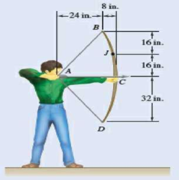
Fig. P7.7
Expert Solution & Answer
Want to see the full answer?
Check out a sample textbook solution
Students have asked these similar questions
Steam flows steadily through a turbine at a rate of 45,000 lbm/h, entering at 1000 psia and 900°F and leaving at 5 psia as saturated vapor. If the power generated by the turbine is 4.1 MW, determine the rate of heat loss from the steam. The enthalpies are h1 = 1448.6 Btu/lbm and h2 = 1130.7 Btu/lbm.
The rate of heat loss from the steam is Btu/s.
The A/D converter wit the specifications listed below is planned to be used in an environment in which the A/D
converter temperature may change by ± 10 °C. Estimate the contributions of conversion and quantization errors
to the uncertainty in the digital representation of an analog voltage by the converter.
FSO
N
Linearity error
Temperature drift error
Analog to Digital (A/D)
Converter
0-10 V
12 bits
± 3 bits
1 bit/5 °C
6-13. A smooth tube in the form of a circle of radius r rotates in its vertical plane with a
constant angular velocity w. The position of a particle of mass m that slides inside
the tube is given by the relative coordinate p. Find the differential equation for .
e
О
E
g
ω
Figure P6-13
Chapter 7 Solutions
VECTOR MECH. FOR EGR: STATS & DYNAM (LL
Ch. 7.1 - 7.1 and 7.2 Determine the internal forces (axial...Ch. 7.1 - 7.1 and 7.2 Determine the internal forces (axial...Ch. 7.1 - Determine the internal forces at point J when =...Ch. 7.1 - Fig. P7.3 and P7.4 7.4 Determine the internal...Ch. 7.1 - Determine the internal forces at point J when =...Ch. 7.1 - Fig. P7.5 and P7.6 7.6 Determine the internal...Ch. 7.1 - An archer aiming at a target is pulling with a...Ch. 7.1 - For the bow of Prob. 7.7, determine the magnitude...Ch. 7.1 - A semicircular rod is loaded as shown. Determine...Ch. 7.1 - A semicircular rod is loaded as shown. Determine...
Ch. 7.1 - A semicircular rod is loaded as shown. Determine...Ch. 7.1 - Fig. P7.11 and P7.12 7.12 A semicircular rod is...Ch. 7.1 - The axis of the curved member AB is a parabola...Ch. 7.1 - Knowing that the axis of the curved member AB is a...Ch. 7.1 - Prob. 7.15PCh. 7.1 - Fig. P7.15 and P7.16 7.16 Knowing that the radius...Ch. 7.1 - Prob. 7.17PCh. 7.1 - For the frame of Prob. 7.17, determine the...Ch. 7.1 - Knowing that the radius of each pulley is 200 mm...Ch. 7.1 - Fig. P7.19 and P7.20 7.20 Knowing that the radius...Ch. 7.1 - and 7.22 A force P is applied to a bent rod that...Ch. 7.1 - and 7.22 A force P is applied to a bent rod that...Ch. 7.1 - Prob. 7.23PCh. 7.1 - For the rod of Prob. 7.23, determine the magnitude...Ch. 7.1 - A semicircular rod of weight W and uniform cross...Ch. 7.1 - Prob. 7.26PCh. 7.1 - Prob. 7.27PCh. 7.1 - 7.27 and 7.28 A half section of pipe rests on a...Ch. 7.2 - 7.29 through 7.32 For the beam and loading shown,...Ch. 7.2 - 7.29 through 7.32 For the beam and loading shown,...Ch. 7.2 - Prob. 7.31PCh. 7.2 - 7.29 through 7.32 For the beam and loading shown,...Ch. 7.2 - 7.33 and 7.34 For the beam and loading shown, (a)...Ch. 7.2 - 7.33 and 7.34 For the beam and loading shown, (a)...Ch. 7.2 - 7.35 and 7.36 For the beam and loading shown, (a)...Ch. 7.2 - Prob. 7.36PCh. 7.2 - 7.37 and 7.38 For the beam and loading shown, (a)...Ch. 7.2 - 7.37 and 7.38 For the beam and loading shown, (a)...Ch. 7.2 - For the beam and loading shown, (a) draw the shear...Ch. 7.2 - For the beam and loading shown, (a) draw the shear...Ch. 7.2 - Prob. 7.41PCh. 7.2 - For the beam and loading shown, (a) draw the shear...Ch. 7.2 - Assuming the upward reaction of the ground on beam...Ch. 7.2 - Solve Problem 7.43 knowing that P = 3wa. PROBLEM...Ch. 7.2 - Assuming the upward reaction of the ground on beam...Ch. 7.2 - Prob. 7.46PCh. 7.2 - Assuming the upward reaction of the ground on beam...Ch. 7.2 - Assuming the upward reaction of the ground on beam...Ch. 7.2 - Draw the shear and bending-moment diagrams for the...Ch. 7.2 - Draw the shear and bending-moment diagrams for the...Ch. 7.2 - Draw the shear and bending-moment diagrams for the...Ch. 7.2 - Draw the shear and bending-moment diagrams for the...Ch. 7.2 - Two small channel sections DF and EH have been...Ch. 7.2 - Solve Prob. 7.53 when = 60. PROBLEM 7.53 Two...Ch. 7.2 - For the structural member of Prob. 7.53, determine...Ch. 7.2 - For the beam of Prob. 7.43, determine (a) the...Ch. 7.2 - Determine (a) the distance a for which the maximum...Ch. 7.2 - For the beam and loading shown, determine (a) the...Ch. 7.2 - A uniform beam is to be picked up by crane cables...Ch. 7.2 - Knowing that P = Q = 150 lb, determine (a) the...Ch. 7.2 - Prob. 7.61PCh. 7.2 - Prob. 7.62PCh. 7.3 - Using the method of Sec. 7.3, solve Prob. 7.29....Ch. 7.3 - Prob. 7.64PCh. 7.3 - Prob. 7.65PCh. 7.3 - Using the method of Sec. 7.3, solve Prob. 7.32....Ch. 7.3 - Using the method of Sec. 7.3, solve Prob. 7.33....Ch. 7.3 - Using the method of Sec. 7.3, solve Prob. 7.34....Ch. 7.3 - 7.69 and 7.70 For the beam and loading shown, (a)...Ch. 7.3 - 7.69 and 7.70 For the beam and loading shown, (a)...Ch. 7.3 - Using the method of Sec. 7.3, solve Prob. 7.39....Ch. 7.3 - Using the method of Sec. 7.3, solve Prob. 7.40....Ch. 7.3 - Using the method of Sec. 7.3, solve Prob. 7.41....Ch. 7.3 - Using the method of Sec. 7.3, solve Prob. 7.42....Ch. 7.3 - 7.75 and 7.76 For the beam and loading shown, (a)...Ch. 7.3 - Prob. 7.76PCh. 7.3 - For the beam and loading shown, (a) draw the shear...Ch. 7.3 - For the beam and loading shown, (a) draw the shear...Ch. 7.3 - For the beam and loading shown, (a) draw the shear...Ch. 7.3 - For the beam and loading shown, (a) draw the shear...Ch. 7.3 - For the beam and loading shown, (a) draw the shear...Ch. 7.3 - For the beam and loading shown, (a) draw the shear...Ch. 7.3 - (a) Draw the shear and bending-moment diagrams for...Ch. 7.3 - Solve Prob. 7.83 assuming that the 300-lb force...Ch. 7.3 - For the beam and loading shown, (a) write the...Ch. 7.3 - For the beam and loading shown, (a) write the...Ch. 7.3 - For the beam and loading shown, (a) write the...Ch. 7.3 - Prob. 7.88PCh. 7.3 - The beam AB supports the uniformly distributed...Ch. 7.3 - Solve Prob. 7.89 assuming that the uniformly...Ch. 7.3 - The beam AB is subjected to the uniformly...Ch. 7.3 - Solve Prob. 7.91 assuming that the uniformly...Ch. 7.4 - Three loads are suspended as shown from the cable...Ch. 7.4 - Knowing that the maximum tension in cable ABCDE is...Ch. 7.4 - Prob. 7.95PCh. 7.4 - Fig. P7.95 and P7.96 7.96 If dA = dc = 6 ft,...Ch. 7.4 - Knowing that dc = 5 m, determine (a) the distances...Ch. 7.4 - Fig. P7.97 and P7.98 7.98 Determine (a) distance...Ch. 7.4 - Knowing that dc = 9 ft, determine (a) the...Ch. 7.4 - Fig. P7.99 and P7.100 7.100 Determine (a) the...Ch. 7.4 - Knowing that mB = 70 kg and mC = 25 kg, determine...Ch. 7.4 - Prob. 7.102PCh. 7.4 - Prob. 7.103PCh. 7.4 - Prob. 7.104PCh. 7.4 - Prob. 7.105PCh. 7.4 - If a = 4 m, determine the magnitudes of P and Q...Ch. 7.4 - An electric wire having a mass per unit length of...Ch. 7.4 - Prob. 7.108PCh. 7.4 - Prob. 7.109PCh. 7.4 - Prob. 7.110PCh. 7.4 - Prob. 7.111PCh. 7.4 - Two cables of the same gauge are attached to a...Ch. 7.4 - Prob. 7.113PCh. 7.4 - Prob. 7.114PCh. 7.4 - Prob. 7.115PCh. 7.4 - Prob. 7.116PCh. 7.4 - Prob. 7.117PCh. 7.4 - Prob. 7.118PCh. 7.4 - Prob. 7.119PCh. 7.4 - Prob. 7.120PCh. 7.4 - Prob. 7.121PCh. 7.4 - Prob. 7.122PCh. 7.4 - Prob. 7.123PCh. 7.4 - Prob. 7.124PCh. 7.4 - Prob. 7.125PCh. 7.4 - Prob. 7.126PCh. 7.5 - A 25-ft chain with a weight of 30 lb is suspended...Ch. 7.5 - A 500-ft-long aerial tramway cable having a weight...Ch. 7.5 - Prob. 7.129PCh. 7.5 - Prob. 7.130PCh. 7.5 - Prob. 7.131PCh. 7.5 - Prob. 7.132PCh. 7.5 - Prob. 7.133PCh. 7.5 - Prob. 7.134PCh. 7.5 - Prob. 7.135PCh. 7.5 - Prob. 7.136PCh. 7.5 - Prob. 7.137PCh. 7.5 - Prob. 7.138PCh. 7.5 - Prob. 7.139PCh. 7.5 - Prob. 7.140PCh. 7.5 - Prob. 7.141PCh. 7.5 - Prob. 7.142PCh. 7.5 - Prob. 7.143PCh. 7.5 - Prob. 7.144PCh. 7.5 - Prob. 7.145PCh. 7.5 - Prob. 7.146PCh. 7.5 - Prob. 7.147PCh. 7.5 - Prob. 7.148PCh. 7.5 - Prob. 7.149PCh. 7.5 - Prob. 7.150PCh. 7.5 - A cable has a mass per unit length of 3 kg/m and...Ch. 7.5 - Prob. 7.152PCh. 7.5 - Prob. 7.153PCh. 7 - Knowing that the turnbuckle has been tightened...Ch. 7 - Knowing that the turnbuckle has been tightened...Ch. 7 - Two members, each consisting of a straight and a...Ch. 7 - Knowing that the radius of each pulley is 150 mm,...Ch. 7 - Prob. 7.158RPCh. 7 - For the beam and loading shown, (a) draw the shear...Ch. 7 - For the beam and loading shown, (a) draw the shear...Ch. 7 - Prob. 7.161RPCh. 7 - Prob. 7.162RPCh. 7 - Prob. 7.163RPCh. 7 - Prob. 7.164RPCh. 7 - A 10-ft rope is attached to two supports A and B...
Knowledge Booster


Learn more about
Need a deep-dive on the concept behind this application? Look no further. Learn more about this topic, mechanical-engineering and related others by exploring similar questions and additional content below.Similar questions
- Problem 2 Consider the power drawn by a resistance load in a DC circuit. The power is calculated as P = VI or P = 1²R. It is given that the normalized uncertainty or % percentage uncertainty in measurements of I, R, and V are the same. Find the uncertainty in P using the two different expressions for power. Is the uncertainty using the two methods the same? If not, WHY, explain?arrow_forwardA piston–cylinder device contains 3 kg of nitrogen initially at 100 kPa and 25°C. Nitrogen is now compressed slowly in a polytropic process during which PV1.3 = constant until the volume is reduced by one-half. Determine the work done and the heat transfer for this process. The gas constant of N2 is R = 0.2968 kPa·m3/kg·K. The cv value of N2 at the anticipated average temperature of 350 K is 0.744 kJ/kg·K (Table A-2b). The work done for this process is kJ. The heat transfer for this process is kJ.arrow_forwardI tried solving this one but I have no idea where I went wrong can you please help me out with this?arrow_forward
- During a picnic on a hot summer day, all the cold drinks disappear quickly, and the only available drinks are those at the ambient temperature of 85°F. In an effort to cool a 12- fluid-oz drink in a can, a person grabs the can and starts shaking it in the iced water of the chest at 32°F. Using the properties of water for the drink, determine the mass of ice that will melt by the time the canned drink cools to 37°F. The density and specific heat of water at the average temperature of (85+37)/2 = 61ºF are ρ = 62.3 lbm/ft3 and cp = 1.0 Btu/lbmºF (Table A-3E). The heat of fusion of water is 143.5 Btu/lbm. The mass of ice that will melt by the time the canned drink cools to 37°F is lbm.arrow_forwardSteam enters a nozzle at 400°C and 800 kPa with a velocity of 10 m/s and leaves at 375°C and 400 kPa while losing heat at a rate of 26.5 kW. For an inlet area of 800 cm2, determine the velocity and the volume flow rate of the steam at the nozzle exit. Use steam tables. At the left side of the lines, 800 kilo Pascal, 400 degree Centigrade, 10 meters per second are shown. At the right side of the lines, 400 kilo Pascal, 375 degree Centigrade are shown. The velocity of the steam at the nozzle exit is m/s. The volume flow rate of the steam at the nozzle exit is m3/s.arrow_forwardA saturated liquid–vapor mixture of water, called wet steam, in a steam line at 1450 kPa is throttled to 50 kPa and 100°C. What is the quality in the steam line? Use data from the steam tables. Above the right side of the tube, 50 kilos 100 degree Centigrade indicated. The quality in the steam line is .arrow_forward
- I tried this problems a couple of ways but I don't know what I'm doing wrong can you help me please?arrow_forwardRefrigerant-134a enters a compressor at 180 kPa as a saturated vapor with a flow rate of 0.35 m3/min and leaves at 900 kPa. The power supplied to the refrigerant during the compression process is 2.35 kW. What is the temperature of R-134a at the exit of the compressor? The temperature of R-134a at the exit of the compressor is °C.arrow_forwardAir enters the compressor of a gas-turbine plant at ambient conditions of 100 kPa and 25°C with a low velocity and exits at 1 MPa and 347°C with a velocity of 90 m/s. The compressor is cooled at a rate of 1500 kJ/min, and the power input to the compressor is 250 kW. Determine the mass flow rate of air through the compressor. The inlet and exit enthalpies of air are 298.2 kJ/kg and 628.07 kJ/kg. The mass flow rate of air is kg/s.arrow_forward
- Consider a 1000-W iron whose base plate is made of 0.5-cm-thick aluminum alloy 2024-T6 (ρ = 2770 kg/m3 and cp = 875 J/kg·°C). The base plate has a surface area of 0.03 m2. Initially, the iron is in thermal equilibrium with the ambient air at 22°C. Assuming 90 percent of the heat generated in the resistance wires is transferred to the plate, determine the minimum time needed for the plate temperature to reach 240°C. The minimum time needed for the plate temperature to reach 240°C is s.arrow_forwardA desktop computer is to be cooled by a fan whose flow rate is 0.34 m3/min. Determine the mass flow rate of air through the fan at an elevation of 3400 m where the air density is 0.7 kg/m3. Also, if the average velocity of air is not to exceed 123 m/min, determine the diameter of the casing of the fan. The mass flow rate of air through the fan is kg/min. The diameter of the casing of the fan is cm.arrow_forwardThe diffuser in a jet engine is designed to decrease the kinetic energy of the air entering the engine compressor without any work or heat interactions. Calculate the velocity at the exit of a diffuser when air at 100 kPa and 30°C enters it with a velocity of 359 m/s and the exit state is 200 kPa and 90°C. The specific heat of air at the average temperature of 60°C = 333 K is cp = 1.007 kJ/kg·K. The velocity at the exit is m/sarrow_forward
arrow_back_ios
SEE MORE QUESTIONS
arrow_forward_ios
Recommended textbooks for you
 Elements Of ElectromagneticsMechanical EngineeringISBN:9780190698614Author:Sadiku, Matthew N. O.Publisher:Oxford University Press
 Mechanics of Materials (10th Edition)Mechanical EngineeringISBN:9780134319650Author:Russell C. HibbelerPublisher:PEARSON
 Thermodynamics: An Engineering ApproachMechanical EngineeringISBN:9781259822674Author:Yunus A. Cengel Dr., Michael A. BolesPublisher:McGraw-Hill Education
 Control Systems EngineeringMechanical EngineeringISBN:9781118170519Author:Norman S. NisePublisher:WILEY
 Mechanics of Materials (MindTap Course List)Mechanical EngineeringISBN:9781337093347Author:Barry J. Goodno, James M. GerePublisher:Cengage Learning
 Engineering Mechanics: StaticsMechanical EngineeringISBN:9781118807330Author:James L. Meriam, L. G. Kraige, J. N. BoltonPublisher:WILEY
Elements Of Electromagnetics
Mechanical Engineering
ISBN:9780190698614
Author:Sadiku, Matthew N. O.
Publisher:Oxford University Press
Mechanics of Materials (10th Edition)
Mechanical Engineering
ISBN:9780134319650
Author:Russell C. Hibbeler
Publisher:PEARSON
Thermodynamics: An Engineering Approach
Mechanical Engineering
ISBN:9781259822674
Author:Yunus A. Cengel Dr., Michael A. Boles
Publisher:McGraw-Hill Education
Control Systems Engineering
Mechanical Engineering
ISBN:9781118170519
Author:Norman S. Nise
Publisher:WILEY
Mechanics of Materials (MindTap Course List)
Mechanical Engineering
ISBN:9781337093347
Author:Barry J. Goodno, James M. Gere
Publisher:Cengage Learning
Engineering Mechanics: Statics
Mechanical Engineering
ISBN:9781118807330
Author:James L. Meriam, L. G. Kraige, J. N. Bolton
Publisher:WILEY
How to balance a see saw using moments example problem; Author: Engineer4Free;https://www.youtube.com/watch?v=d7tX37j-iHU;License: Standard Youtube License