
Videos
(a)
The internal forces exerted at the point
(a)
Answer to Problem 7.15P
The internal forces of shearing force is
Explanation of Solution
Sketch the free body diagram for the internal forces acting on the frame and pulley system as shown in the Figure 1.
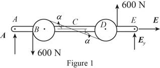
Write the equation of the axial force exerted at the axial point
Here, the force exerted on the frame at the point
Write the equation of the moment of couple formed in the bending moment of the frame and pulley system supported at the point
Here, the axial force exerted on the pulley at point
Write the equation of the axial force exerted at the axial point of the frame from y direction (Refer fig 1).
Here, the axial force exerted on the pulley at point
Sketch the free body diagram for the cable as shown in the Figure 2.
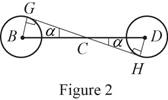
The slope of the cable (Refer fig 2):
The angle formed in the slope of the cable:
Rewrite the above relation to find the angle.
Write the equation of the axial force exerted at the axial point
Here, the angle between the pulley
Sketch the free body diagram for the cable for the point
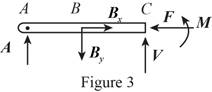
Write the equation of the axial force exerted at the point
Here, shearing force acting on the semicircular rod is
At the pulley
Write the equation of the moment of couple formed in the bending moment supported at the point
Here, the moment of couple exerted at the point
Conclusion:
Substitute
Solve the above equation for
Substitute
Substitute
Substitute
Substitute
The above equation can be written as,
Therefore, the internal forces of shearing force is
(b)
The internal forces exerted at the point
(b)
Answer to Problem 7.15P
The internal forces of shearing force is
Explanation of Solution
Sketch the free body diagram for the cable for the point
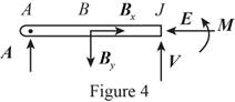
Write the equation of the axial force exerted at the axial point
Here, the force exerted on the frame at the point
Write the equation of the axial force exerted at the axial point of the frame from y direction (Refer fig 4).
Here, the axial force exerted on the pulley at point
Write the equation of the moment of couple formed in the bending moment supported at the point
Here, the moment of couple exerted at the point
Conclusion:
Substitute
Substitute
Substitute
The above equation can be written as,
Therefore, the internal forces of shearing force is
Want to see more full solutions like this?
Chapter 7 Solutions
Vector Mechanics for Engineers: Statics and Dynamics


- my ID# is 016948724 please solve this problem step by steparrow_forwardMY ID#016948724 please solve the problem step by spetarrow_forward1 8 4 For the table with 4×4 rows and columns as shown Add numbers so that the sum of any row or column equals .30 Use only these numbers: .1.2.3.4.5.6.10.11.12.12.13.14.14arrow_forward
- MY ID# 016948724 please solve this problem step by steparrow_forwardThe pickup truck weighs 3220 Ib and reaches a speed of 30 mi/hr from rest in a distance of 200 ft up the 10-percent incline with constant acceleration. Calculate the normal force under each pair of wheels and the friction force under the rear driving wheels. The effective coefficient of friction between the tires and the road is known to be at least 0.8.arrow_forward1. The figure shows a car jack to support 400kg (W=400kg). In the drawing, the angle (0) varies between 15 and 70 °. The links are machined from AISI 1020 hot-rolled steel bars with a minimum yield strength of 380MPa. Each link consists of two bars, one on each side of the central bearings. The bars are 300mm in length (/) and 25 mm in width (w). The pinned ends have the buckling constant (C) of 1.4 for out of plane buckling. The design factor (nd) is 2.5. (1) Find the thickness (t) of the bars and the factor of safety (n). (2) Check if the bar is an Euler beam. Darrow_forward
- (Read image)arrow_forwardUNIVERSIDAD NACIONAL DE SAN ANTONIO ABAD DEL CUSCO PRIMER EXAMEN PARCIAL DE MECÁNICA DE FLUIDOS I ............ Cusco, 23 de setiembre de 2024 AP. Y NOMBRES: ........ 1.- Para el tanque de la figura: a) Calcule la profundidad de la hidrolina si la profundidad del agua es de 2.8 m y el medidor del fondo del tanque da una lectura de 52.3kPa. b) Calcule la profundidad del agua si la profundidad de la hidrolina es 6.90 m y el medidor de la parte inferior del tanque registra una lectura de 125.3 kPa. Hidrolina Sp=0.90 Abertura Agua sup suge to but amulor quit y 2.- Calcule la magnitud de la fuerza resultante sobre el área A-B y la ubicación del centro de presión. Señale la fuerza resultante sobre el área y dimensione su ubicación con claridad. 3.5 ft 12 in: Oil (38-0.93) 14 in 8 inarrow_forwardplease solve this problem and give me the correct answer step by steparrow_forward
 Elements Of ElectromagneticsMechanical EngineeringISBN:9780190698614Author:Sadiku, Matthew N. O.Publisher:Oxford University Press
 Mechanics of Materials (10th Edition)Mechanical EngineeringISBN:9780134319650Author:Russell C. HibbelerPublisher:PEARSON
 Thermodynamics: An Engineering ApproachMechanical EngineeringISBN:9781259822674Author:Yunus A. Cengel Dr., Michael A. BolesPublisher:McGraw-Hill Education
 Control Systems EngineeringMechanical EngineeringISBN:9781118170519Author:Norman S. NisePublisher:WILEY
 Mechanics of Materials (MindTap Course List)Mechanical EngineeringISBN:9781337093347Author:Barry J. Goodno, James M. GerePublisher:Cengage Learning
 Engineering Mechanics: StaticsMechanical EngineeringISBN:9781118807330Author:James L. Meriam, L. G. Kraige, J. N. BoltonPublisher:WILEY