Precision Machining Technology
3rd Edition
ISBN: 9781337795302
Author: Peter, Hoffman.
Publisher: Cengage Learning,
expand_more
expand_more
format_list_bulleted
Textbook Question
Chapter 7.1, Problem 5RQ
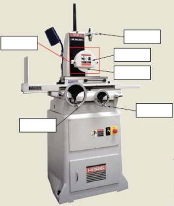
Label the parts of the surface grinder.

Expert Solution & Answer
Trending nowThis is a popular solution!

Students have asked these similar questions
##2# Superheated steam powers a steam turbine for the production of electrical energy. The steam expands in the turbine and at an intermediate expansion pressure (0.1 Mpa) a fraction is extracted for a regeneration process in a surface regenerator. The turbine has an isentropic efficiency of 90%
Design the simplified power plant schematic
Analyze it on the basis of the attached figure
Determine the power generated and the thermal efficiency of the plant
### Dados in the attached images
### To make a conclusion for a report of an experiment on rockets, in which the openrocket software was used for the construction and modeling of two rockets: one one-stage and one two-stage.
First rocket (single-stage) reached a maximum vertical speed of 100 m/s and a maximum height of 500 m
The second rocket (two-stage) reached a maximum vertical speed of 50 m/s and a maximum height of 250 m
To make a simplified conclusion, taking into account the efficiency of the software in the study of rockets
Determine the coefficients of polynomial for the polynomial function of Cam profile based on
the boundary conditions shown in the figure.
S
a
3
4
5
C₁
(+)
Ꮎ
В
s = q + q { + c f * + q € * + q ( +c+c+c
6
Ꮎ
+C5
+C
β
В
В
0
cam angle 0
B
7
(
Chapter 7 Solutions
Precision Machining Technology
Ch. 7.1 - What are three benefits of precision grinding?Ch. 7.1 - What is the major use of the surface grinder?Ch. 7.1 - What are the two spindle types used for surface...Ch. 7.1 - What are the two types of table movements used for...Ch. 7.1 - Label the parts of the surface grinder.Ch. 7.1 - What are three types of cylindrical grinders?Ch. 7.1 - Tool and cutter grinders can be used to _______...Ch. 7.2 - What wheel shapes are commonly used for surface...Ch. 7.2 - What abrasive is commonly used to grind steels?Ch. 7.2 - What abrasive is used to grind nonferrous metals,...
Ch. 7.2 - What does CBN stand for?Ch. 7.2 - What superabrasive is a good choice for grinding...Ch. 7.2 - The grade of a wheel describes its __________ on a...Ch. 7.2 - Prob. 7RQCh. 7.2 - Prob. 8RQCh. 7.2 - Generally, harder wheels should be used to grind...Ch. 7.2 - Wheel A: 32A60H8V Wheel B: 39C100L6V What is the...Ch. 7.2 - Wheel A: 32A60H8V Wheel B: 39C100L6V Which wheel...Ch. 7.2 - Wheel A: 32A60H8V Wheel B: 39C100L6V Which wheel...Ch. 7.2 - Wheel A: 32A60H8V Wheel B: 39C100L6V Which wheel...Ch. 7.2 - Wheel A: 32A60H8V Wheel B: 39C100L6V What type of...Ch. 7.3 - List five surface grinder safety guidelines.Ch. 7.3 - What should be done to every grinding wheel before...Ch. 7.3 - When using a magnetic workholding device, the work...Ch. 7.3 - When using a magnetic chuck to hold a workpiece...Ch. 7.3 - Describe the difference between wheel truing and...Ch. 7.3 - What tool is used to true and dress an aluminum...Ch. 7.3 - How is a CBN wheel trued and dressed?Ch. 7.3 - Depth-of-cut range for surface grinding is: a....Ch. 7.3 - What should be done to a magnetic chuck when it...Ch. 7.3 - What workholding device can extend the magnetic...Ch. 7.3 - What workholding device can be used when grinding...Ch. 7.3 - Briefly describe the method for grinding two...Ch. 7.3 - List three types of workpiece features that can be...Ch. 7.3 - List three possible solutions to eliminate bum...Ch. 7.3 - What can cause scratches on the surface of a...
Knowledge Booster
Learn more about
Need a deep-dive on the concept behind this application? Look no further. Learn more about this topic, mechanical-engineering and related others by exploring similar questions and additional content below.Similar questions
- ### Superheated steam powers a steam turbine for the production of electrical energy. The steam expands in the turbine and at an intermediate expansion pressure (0.1 Mpa) a fraction is extracted for a regeneration process in a surface regenerator. The turbine has an isentropic efficiency of 90% Design the simplified power plant schematic Analyze it on the basis of the attached figure Determine the power generated and the thermal efficiency of the plant ### Dados in the attached imagesarrow_forwardThe machine below forms metal plates through the application of force. Two toggles (ABC and DEF) transfer forces from the central hydraulic cylinder (H) to the plates that will be formed. The toggles then push bar G to the right, which then presses a plate (p) into the cavity, thus shaping it. In this case, the plate becomes a section of a sphere. If the hydraulic cylinder can produce a maximum force of F = 10 kN, then what is the maximum P value (i.e. Pmax) that can be applied to the plate when θ = 35°? Also, what are the compressive forces in the toggle rods in that situation? Finally, what happens to Pmax and the forces in the rods as θ decreases in magnitude?arrow_forwardDetermine the magnitude of the minimum force P needed to prevent the 20 kg uniform rod AB from sliding. The contact surface at A is smooth, whereas the coefficient of static friction between the rod and the floor is μs = 0.3.arrow_forward
- Determine the magnitudes of the reactions at the fixed support at A.arrow_forwardLet Hill frame H = {i-hat_r, i-hat_θ, i-hat_h} be the orbit frame of the LMO satellite. These base vectors are generally defined as:i-hat_r = r_LM / |r_LM|, i-hat_theta = i-hat_h X i-hat_r, i-hat_h = r_LM X r-dot_LMO /( | r_LM X r-dot_LMO | ) How would you: • Determine an analytic expressions for [HN]arrow_forwardDe Moivre’s Theoremarrow_forward
- hand-written solutions only, please.arrow_forwardDetermine the shear flow qqq for the given profile when the shear forces acting at the torsional center are Qy=30Q_y = 30Qy=30 kN and Qz=20Q_z = 20Qz=20 kN. Also, calculate qmaxq_{\max}qmax and τmax\tau_{\max}τmax. Given:Iy=10.5×10⁶I_y = 10.5 \times 10^6Iy=10.5×106 mm4^44,Iz=20.8×10⁶I_z = 20.8 \times 10^6Iz=20.8×106 mm4^44,Iyz=6×10⁶I_{yz} = 6 \times 10^6Iyz=6×106 mm4^44. Additional parameters:αy=0.5714\alpha_y = 0.5714αy=0.5714,αz=0.2885\alpha_z = 0.2885αz=0.2885,γ=1.1974\gamma = 1.1974γ=1.1974. (Check hint: τmax\tau_{\max}τmax should be approximately 30 MPa.)arrow_forwardhand-written solutions only, please.arrow_forward
- In the bending of a U-profile beam, the load path passes through the torsional center C, causing a moment of 25 kNm at the cross-section under consideration. Additionally, the beam is subjected to an axial tensile force of 100 kN at the centroid. Determine the maximum absolute normal stress.(Check hint: approximately 350 MPa, but where?)arrow_forward### Make an introduction to a report of a rocket study project, in the OpenRocket software, where the project consists of the simulation of single-stage and two-stage rockets, estimating the values of the exhaust velocities of the engines used, as well as obtaining the graphs of "altitude", "mass ratio x t", "thrust x t" and "ψ × t".arrow_forwardA 6305 ball bearing is subjected to a steady 5000-N radial load and a 2000-N thrust load and uses a very clean lubricant throughout its life. If the inner race angular velocity is 500 rpm find The equivalent radial load the L10 life and the L50 lifearrow_forward
arrow_back_ios
SEE MORE QUESTIONS
arrow_forward_ios
Recommended textbooks for you
 Precision Machining Technology (MindTap Course Li...Mechanical EngineeringISBN:9781285444543Author:Peter J. Hoffman, Eric S. Hopewell, Brian JanesPublisher:Cengage Learning
 Welding: Principles and Applications (MindTap Cou...Mechanical EngineeringISBN:9781305494695Author:Larry JeffusPublisher:Cengage Learning
 Refrigeration and Air Conditioning Technology (Mi...Mechanical EngineeringISBN:9781305578296Author:John Tomczyk, Eugene Silberstein, Bill Whitman, Bill JohnsonPublisher:Cengage Learning

Precision Machining Technology (MindTap Course Li...
Mechanical Engineering
ISBN:9781285444543
Author:Peter J. Hoffman, Eric S. Hopewell, Brian Janes
Publisher:Cengage Learning

Welding: Principles and Applications (MindTap Cou...
Mechanical Engineering
ISBN:9781305494695
Author:Larry Jeffus
Publisher:Cengage Learning

Refrigeration and Air Conditioning Technology (Mi...
Mechanical Engineering
ISBN:9781305578296
Author:John Tomczyk, Eugene Silberstein, Bill Whitman, Bill Johnson
Publisher:Cengage Learning
HOME SHOP JIGS & FIXTURES PART 1, TYPES OF JIGS & ACCESSORIES AND THE THEORIE BEHIND THE TOOLS; Author: THATLAZYMACHINIST;https://www.youtube.com/watch?v=EXYqi42JimI;License: Standard Youtube License