ENGR.MECH.:STAT.+DYNAMICS
15th Edition
ISBN: 9780134780955
Author: HIBBELER
Publisher: RENT PEARS
expand_more
expand_more
format_list_bulleted
Concept explainers
Videos
Textbook Question
Chapter 7, Problem 88P
Draw the shear and moment diagrams for the beam.
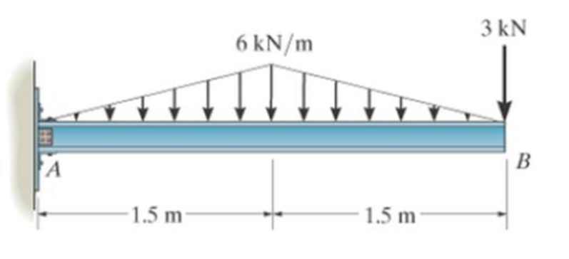
Prob. 7–88
Expert Solution & Answer
Want to see the full answer?
Check out a sample textbook solution
Students have asked these similar questions
Auto Controls
Using MATLAB , find the magnitude and phase plot of the compensators
NO COPIED SOLUTIONS
4-81 The corner shown in Figure P4-81 is initially uniform at 300°C and then suddenly
exposed to a convection environment at 50°C with h 60 W/m². °C. Assume the
=
2
solid has the properties of fireclay brick. Examine nodes 1, 2, 3, 4, and 5 and deter-
mine the maximum time increment which may be used for a transient numerical
calculation.
Figure P4-81
1
2
3
4
1 cm
5
6
1 cm
2 cm
h, T
+
2 cm
Auto Controls
A union feedback control system has the following open loop transfer function
where k>0 is a variable proportional gain
i. for K = 1 , derive the exact magnitude and phase expressions of G(jw).
ii) for K = 1 , identify the gaincross-over frequency (Wgc) [where IG(jo))| 1] and phase cross-overfrequency [where <G(jw) = - 180]. You can use MATLAB command "margin" to obtain there quantities.
iii) Calculate gain margin (in dB) and phase margin (in degrees) ·State whether the closed-loop is stable for K = 1 and briefly justify your answer based on the margin . (Gain marginPhase margin)
iv. what happens to the gain margin and Phase margin when you increase the value of K?you
You can use for loop in MATLAB to check that.Helpful matlab commands : if, bode, margin, rlocus
NO COPIED SOLUTIONS
Chapter 7 Solutions
ENGR.MECH.:STAT.+DYNAMICS
Ch. 7 - Determine the normal force, shear force, and...Ch. 7 - Determine the normal force, shear force, and...Ch. 7 - Determine the normal force, shear force, and...Ch. 7 - Determine the normal force, shear force, and...Ch. 7 - Determine the normal force, shear force, and...Ch. 7 - Determine the normal force, shear force, and...Ch. 7 - Determine the shear force and moment at points C...Ch. 7 - The pliers are used to grip the tube at B. If a...Ch. 7 - Determine the distance a as a fraction of the...Ch. 7 - The cable will fail when subjected to a tension of...
Ch. 7 - Determine the distance a between the bearings in...Ch. 7 - The cantilevered rack is used to support each end...Ch. 7 - Rod AB is fixed to a smooth collar D, which slides...Ch. 7 - Prob. 22PCh. 7 - Determine the normal force, shear force, and...Ch. 7 - The distributed loading W = W0 sin , measured per...Ch. 7 - Solve Prob. 7-39 for = 120. Probs. 739/40Ch. 7 - Determine the x, y, z components of force and...Ch. 7 - Determine the x, y, z components of internal...Ch. 7 - Determine the shear and moment as a function of x,...Ch. 7 - Determine the shear and moment as a function of x,...Ch. 7 - Determine the shear and moment as a function of x,...Ch. 7 - Determine the shear and moment as a function of x,...Ch. 7 - Determine the shear and moment as a function of x,...Ch. 7 - Determine the shear and moment as a function of x,...Ch. 7 - Draw the shear and moment diagrams for the shaft...Ch. 7 - Draw the shear and moment diagrams for the beam...Ch. 7 - Draw the shear and moment diagrams for the beam...Ch. 7 - Draw the shear and moment diagrams for the...Ch. 7 - Draw the shear and moment diagrams of the beam (a)...Ch. 7 - If L = 9 m, the beam will fail when the maximum...Ch. 7 - Draw the shear and moment diagrams for the beam....Ch. 7 - Draw the shear and moment diagrams for the beam....Ch. 7 - The shaft is supported by a smooth thrust bearing...Ch. 7 - Draw the shear and moment diagrams for the beam....Ch. 7 - Prob. 58PCh. 7 - Prob. 59PCh. 7 - The shaft is supported by a smooth thrust bearing...Ch. 7 - Draw the shear and moment diagrams for the beam....Ch. 7 - Prob. 65PCh. 7 - Draw the shear and moment diagrams for the beam....Ch. 7 - Draw the shear and moment diagrams for the beam....Ch. 7 - Draw the shear and moment diagrams for the beam....Ch. 7 - Draw the shear and moment diagrams for the beam....Ch. 7 - Draw the shear and moment diagrams for the beam....Ch. 7 - Draw the shear and moment diagrams for the beam....Ch. 7 - Draw the shear and moment diagrams for the beam....Ch. 7 - Draw the shear and moment diagrams for the beam....Ch. 7 - Draw the shear and moment diagrams for the beam....Ch. 7 - Draw the shear and moment diagrams for the beam....Ch. 7 - Draw the shear and moment diagrams for the beam....Ch. 7 - Draw the shear and moment diagrams for the beam....Ch. 7 - Draw the shear and moment diagrams for the beam....Ch. 7 - The cable supports the three loads shown....Ch. 7 - Prob. 95PCh. 7 - Determine the tension in each segment of the cable...Ch. 7 - Prob. 97PCh. 7 - The cable supports the loading shown. Determine...Ch. 7 - The cable supports the three loads shown....Ch. 7 - The cable supports the three loads shown....Ch. 7 - Determine the maximum uniform loading w, measured...Ch. 7 - The cable is subjected to a uniform loading of w =...Ch. 7 - If x = 2 ft and the crate weighs 300 lb, which...Ch. 7 - If yB = 1.5 ft. determine the largest weight of...Ch. 7 - The cable supports a girder which weighs 850...Ch. 7 - If the pipe has a mass per unit length of 1500...Ch. 7 - Prob. 110PCh. 7 - The cable will break when the maximum tension...Ch. 7 - Prob. 2RPCh. 7 - Prob. 3RPCh. 7 - Prob. 4RPCh. 7 - Draw the shear and moment diagrams for the beam....Ch. 7 - A chain is suspended between points at the same...
Knowledge Booster


Learn more about
Need a deep-dive on the concept behind this application? Look no further. Learn more about this topic, mechanical-engineering and related others by exploring similar questions and additional content below.Similar questions
- Auto Controls Hand sketch the root Focus of the following transfer function How many asymptotes are there ?what are the angles of the asymptotes?Does the system remain stable for all values of K NO COPIED SOLUTIONSarrow_forward-400" 150" in Datum 80" 90" -280"arrow_forwardUsing hand drawing both of themarrow_forward
- A 10-kg box is pulled along P,Na rough surface by a force P, as shown in thefigure. The pulling force linearly increaseswith time, while the particle is motionless att = 0s untilit reaches a maximum force of100 Nattimet = 4s. If the ground has staticand kinetic friction coefficients of u, = 0.6 andHU, = 0.4 respectively, determine the velocityof the A 1 0 - kg box is pulled along P , N a rough surface by a force P , as shown in the figure. The pulling force linearly increases with time, while the particle is motionless at t = 0 s untilit reaches a maximum force of 1 0 0 Nattimet = 4 s . If the ground has static and kinetic friction coefficients of u , = 0 . 6 and HU , = 0 . 4 respectively, determine the velocity of the particle att = 4 s .arrow_forwardCalculate the speed of the driven member with the following conditions: Diameter of the motor pulley: 4 in Diameter of the driven pulley: 12 in Speed of the motor pulley: 1800 rpmarrow_forward4. In the figure, shaft A made of AISI 1010 hot-rolled steel, is welded to a fixed support and is subjected to loading by equal and opposite Forces F via shaft B. Stress concentration factors K₁ (1.7) and Kts (1.6) are induced by the 3mm fillet. Notch sensitivities are q₁=0.9 and qts=1. The length of shaft A from the fixed support to the connection at shaft B is 1m. The load F cycles from 0.5 to 2kN and a static load P is 100N. For shaft A, find the factor of safety (for infinite life) using the modified Goodman fatigue failure criterion. 3 mm fillet Shaft A 20 mm 25 mm Shaft B 25 mmarrow_forward
arrow_back_ios
SEE MORE QUESTIONS
arrow_forward_ios
Recommended textbooks for you
 Elements Of ElectromagneticsMechanical EngineeringISBN:9780190698614Author:Sadiku, Matthew N. O.Publisher:Oxford University Press
 Mechanics of Materials (10th Edition)Mechanical EngineeringISBN:9780134319650Author:Russell C. HibbelerPublisher:PEARSON
 Thermodynamics: An Engineering ApproachMechanical EngineeringISBN:9781259822674Author:Yunus A. Cengel Dr., Michael A. BolesPublisher:McGraw-Hill Education
 Control Systems EngineeringMechanical EngineeringISBN:9781118170519Author:Norman S. NisePublisher:WILEY
 Mechanics of Materials (MindTap Course List)Mechanical EngineeringISBN:9781337093347Author:Barry J. Goodno, James M. GerePublisher:Cengage Learning
 Engineering Mechanics: StaticsMechanical EngineeringISBN:9781118807330Author:James L. Meriam, L. G. Kraige, J. N. BoltonPublisher:WILEY
Elements Of Electromagnetics
Mechanical Engineering
ISBN:9780190698614
Author:Sadiku, Matthew N. O.
Publisher:Oxford University Press
Mechanics of Materials (10th Edition)
Mechanical Engineering
ISBN:9780134319650
Author:Russell C. Hibbeler
Publisher:PEARSON
Thermodynamics: An Engineering Approach
Mechanical Engineering
ISBN:9781259822674
Author:Yunus A. Cengel Dr., Michael A. Boles
Publisher:McGraw-Hill Education
Control Systems Engineering
Mechanical Engineering
ISBN:9781118170519
Author:Norman S. Nise
Publisher:WILEY
Mechanics of Materials (MindTap Course List)
Mechanical Engineering
ISBN:9781337093347
Author:Barry J. Goodno, James M. Gere
Publisher:Cengage Learning
Engineering Mechanics: Statics
Mechanical Engineering
ISBN:9781118807330
Author:James L. Meriam, L. G. Kraige, J. N. Bolton
Publisher:WILEY
Understanding Shear Force and Bending Moment Diagrams; Author: The Efficient Engineer;https://www.youtube.com/watch?v=C-FEVzI8oe8;License: Standard YouTube License, CC-BY
Bending Stress; Author: moodlemech;https://www.youtube.com/watch?v=9QIqewkE6xM;License: Standard Youtube License