ENGR.MECH.:STAT.+DYNAMICS
15th Edition
ISBN: 9780134780955
Author: HIBBELER
Publisher: RENT PEARS
expand_more
expand_more
format_list_bulleted
Concept explainers
Videos
Textbook Question
Chapter 7, Problem 40P
Solve Prob. 7-39 for θ = 120°.
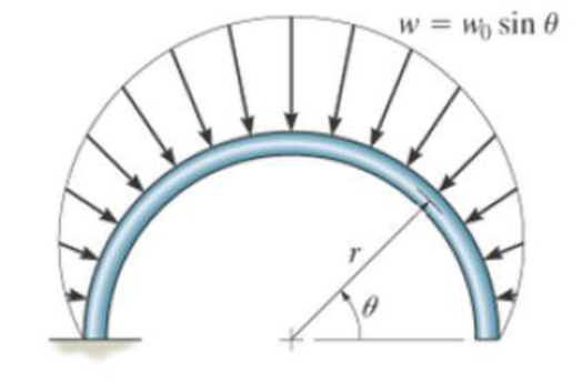
Probs. 7–39/40
Expert Solution & Answer
Want to see the full answer?
Check out a sample textbook solution
Students have asked these similar questions
A boiler with 80% efficiency produces steam at 40bar and 500 C at a rate of 1.128kg/s.
The temperature of the feed water is raised from 25 C to 125 C in the economizer and the
ambient air is drawn to the boiler at a rate of 2.70 kg/s at 16 C. The flue gases leave the
chimney at rate of 3 kg/s at 150 C with specific heat of 1.01 kJ/kg.K. The dryness fraction
of steam collected in the steam drum is 0.95.
1- Determine the heat value of the fuel.
2- The equivalence evaporation.
3- Draw the heat balance sheet.
A rotating shaft is made of 42 mm by 4 mm thick cold-drawn round steel tubing and has a 6 mm diameter
hole drilled transversely through it. The shaft is subjected to a pulsating torque fluctuating from 20 to 160
Nm and a completely reversed bending moment of 200 Nm. The steel tubing has a minimum strength of Sut
= 410 MPa (60 ksi). The static stress-concentration factor for the hole is 2.4 for bending and 1.9 for torsion.
The maximum operating temperature is 400˚C and a reliability of 99.9% is to be assumed. Find the factor of
safety for infinite life using the modified Goodman failure criterion.
I need help with a MATLAB code. This code just keeps running and does not give me any plots. I even reduced the tolerance from 1e-9 to 1e-6. Can you help me fix this? Please make sure your solution runs.
% Initial Conditions
rev = 0:0.001:2;
g1 = deg2rad(1);
g2 = deg2rad(3);
g3 = deg2rad(6);
g4 = deg2rad(30);
g0 = deg2rad(0);
Z0 = 0;
w0 = [0; Z0*cos(g0); -Z0*sin(g0)];
Z1 = 5;
w1 = [0; Z1*cos(g1); -Z1*sin(g1)];
Z2 = 11;
w2 = [0; Z2*cos(g2); -Z2*sin(g2)];
[v3, psi3, eta3] = Nut_angle(Z2, g2, w2);
plot(v3, psi3)
function dwedt = K_DDE(~, w_en)
% Extracting the initial condtions to a variable
% Extracting the initial condtions to a variable
w = w_en(1:3);
e = w_en(4:7);
Z = w_en(8);
I = 0.060214;
J = 0.015707;
x = (J/I) - 1;
y = Z - 1;
s = Z;
% Kinematic Differential Equations
dedt = zeros(4,1);
dedt(1) = pi*(e(3)*(s-w(2)-1) + e(2)*w(3) + e(4)*w(1));
dedt(2) = pi*(e(4)*(w(2)-1-s) + e(3)*w(1) - e(1)*w(3));
dedt(3) = pi*(-e(1)*(s-w(2)-1) - e(2)*w(1) + e(4)*w(3));…
Chapter 7 Solutions
ENGR.MECH.:STAT.+DYNAMICS
Ch. 7 - Determine the normal force, shear force, and...Ch. 7 - Determine the normal force, shear force, and...Ch. 7 - Determine the normal force, shear force, and...Ch. 7 - Determine the normal force, shear force, and...Ch. 7 - Determine the normal force, shear force, and...Ch. 7 - Determine the normal force, shear force, and...Ch. 7 - Determine the shear force and moment at points C...Ch. 7 - The pliers are used to grip the tube at B. If a...Ch. 7 - Determine the distance a as a fraction of the...Ch. 7 - The cable will fail when subjected to a tension of...
Ch. 7 - Determine the distance a between the bearings in...Ch. 7 - The cantilevered rack is used to support each end...Ch. 7 - Rod AB is fixed to a smooth collar D, which slides...Ch. 7 - Prob. 22PCh. 7 - Determine the normal force, shear force, and...Ch. 7 - The distributed loading W = W0 sin , measured per...Ch. 7 - Solve Prob. 7-39 for = 120. Probs. 739/40Ch. 7 - Determine the x, y, z components of force and...Ch. 7 - Determine the x, y, z components of internal...Ch. 7 - Determine the shear and moment as a function of x,...Ch. 7 - Determine the shear and moment as a function of x,...Ch. 7 - Determine the shear and moment as a function of x,...Ch. 7 - Determine the shear and moment as a function of x,...Ch. 7 - Determine the shear and moment as a function of x,...Ch. 7 - Determine the shear and moment as a function of x,...Ch. 7 - Draw the shear and moment diagrams for the shaft...Ch. 7 - Draw the shear and moment diagrams for the beam...Ch. 7 - Draw the shear and moment diagrams for the beam...Ch. 7 - Draw the shear and moment diagrams for the...Ch. 7 - Draw the shear and moment diagrams of the beam (a)...Ch. 7 - If L = 9 m, the beam will fail when the maximum...Ch. 7 - Draw the shear and moment diagrams for the beam....Ch. 7 - Draw the shear and moment diagrams for the beam....Ch. 7 - The shaft is supported by a smooth thrust bearing...Ch. 7 - Draw the shear and moment diagrams for the beam....Ch. 7 - Prob. 58PCh. 7 - Prob. 59PCh. 7 - The shaft is supported by a smooth thrust bearing...Ch. 7 - Draw the shear and moment diagrams for the beam....Ch. 7 - Prob. 65PCh. 7 - Draw the shear and moment diagrams for the beam....Ch. 7 - Draw the shear and moment diagrams for the beam....Ch. 7 - Draw the shear and moment diagrams for the beam....Ch. 7 - Draw the shear and moment diagrams for the beam....Ch. 7 - Draw the shear and moment diagrams for the beam....Ch. 7 - Draw the shear and moment diagrams for the beam....Ch. 7 - Draw the shear and moment diagrams for the beam....Ch. 7 - Draw the shear and moment diagrams for the beam....Ch. 7 - Draw the shear and moment diagrams for the beam....Ch. 7 - Draw the shear and moment diagrams for the beam....Ch. 7 - Draw the shear and moment diagrams for the beam....Ch. 7 - Draw the shear and moment diagrams for the beam....Ch. 7 - Draw the shear and moment diagrams for the beam....Ch. 7 - The cable supports the three loads shown....Ch. 7 - Prob. 95PCh. 7 - Determine the tension in each segment of the cable...Ch. 7 - Prob. 97PCh. 7 - The cable supports the loading shown. Determine...Ch. 7 - The cable supports the three loads shown....Ch. 7 - The cable supports the three loads shown....Ch. 7 - Determine the maximum uniform loading w, measured...Ch. 7 - The cable is subjected to a uniform loading of w =...Ch. 7 - If x = 2 ft and the crate weighs 300 lb, which...Ch. 7 - If yB = 1.5 ft. determine the largest weight of...Ch. 7 - The cable supports a girder which weighs 850...Ch. 7 - If the pipe has a mass per unit length of 1500...Ch. 7 - Prob. 110PCh. 7 - The cable will break when the maximum tension...Ch. 7 - Prob. 2RPCh. 7 - Prob. 3RPCh. 7 - Prob. 4RPCh. 7 - Draw the shear and moment diagrams for the beam....Ch. 7 - A chain is suspended between points at the same...
Knowledge Booster


Learn more about
Need a deep-dive on the concept behind this application? Look no further. Learn more about this topic, mechanical-engineering and related others by exploring similar questions and additional content below.Similar questions
- alpha 1 is not zero alpha 1 can equal alpha 2 use velocity triangle to solve for alpha 1 USE MATLAB ONLY provide typed code solve for velocity triangle and dont provide copied answer Turbomachienery . GIven: vx = 185 m/s, flow angle = 60 degrees, (leaving a stator in axial flow) R = 0.5, U = 150 m/s, b2 = -a3, a2 = -b3 Find: velocity triangle , a. magnitude of abs vel leaving rotor (m/s) b. flow absolute angles (a1, a2, a3) 3. flow rel angles (b2, b3) d. specific work done e. use code to draw vel. diagram Use this code for plot % plots Velocity Tri. in Ch4 function plotveltri(al1,al2,al3,b2,b3) S1L = [0 1]; V1x = [0 0]; V1s = [0 1*tand(al3)]; S2L = [2 3]; V2x = [0 0]; V2s = [0 1*tand(al2)]; W2s = [0 1*tand(b2)]; U2x = [3 3]; U2y = [1*tand(b2) 1*tand(al2)]; S3L = [4 5]; V3x = [0 0]; V3r = [0 1*tand(al3)]; W3r = [0 1*tand(b3)]; U3x = [5 5]; U3y = [1*tand(b3) 1*tand(al3)]; plot(S1L,V1x,'k',S1L,V1s,'r',... S2L,V2x,'k',S2L,V2s,'r',S2L,W2s,'b',U2x,U2y,'g',...…arrow_forward3. Find a basis of eigenvectors and diagonalize. 4 0 -19 7 a. b. 1-42 16 12-20 [21-61arrow_forward2. Find the eigenvalues. Find the corresponding eigenvectors. 6 2 -21 [0 -3 1 3 31 a. 2 5 0 b. 3 0 -6 C. 1 1 0 -2 0 7 L6 6 0 1 1 2. (Hint: λ = = 3)arrow_forward
- USE MATLAB ONLY provide typed code solve for velocity triangle and dont provide copied answer Turbomachienery . GIven: vx = 185 m/s, flow angle = 60 degrees, (leaving a stator in axial flow) R = 0.5, U = 150 m/s, b2 = -a3, a2 = -b3 Find: velocity triangle , a. magnitude of abs vel leaving rotor (m/s) b. flow absolute angles (a1, a2, a3) 3. flow rel angles (b2, b3) d. specific work done e. use code to draw vel. diagram Use this code for plot % plots Velocity Tri. in Ch4 function plotveltri(al1,al2,al3,b2,b3) S1L = [0 1]; V1x = [0 0]; V1s = [0 1*tand(al3)]; S2L = [2 3]; V2x = [0 0]; V2s = [0 1*tand(al2)]; W2s = [0 1*tand(b2)]; U2x = [3 3]; U2y = [1*tand(b2) 1*tand(al2)]; S3L = [4 5]; V3x = [0 0]; V3r = [0 1*tand(al3)]; W3r = [0 1*tand(b3)]; U3x = [5 5]; U3y = [1*tand(b3) 1*tand(al3)]; plot(S1L,V1x,'k',S1L,V1s,'r',... S2L,V2x,'k',S2L,V2s,'r',S2L,W2s,'b',U2x,U2y,'g',... S3L,V3x,'k',S3L,V3r,'r',S3L,W3r,'b',U3x,U3y,'g',...... 'LineWidth',2,'MarkerSize',10),...…arrow_forwardUSE MATLAB ONLY provide typed code solve for velocity triangle and dont provide copied answer Turbomachienery . GIven: vx = 185 m/s, flow angle = 60 degrees, R = 0.5, U = 150 m/s, b2 = -a3, a2 = -b3 Find: velocity triangle , a. magnitude of abs vel leaving rotor (m/s) b. flow absolute angles (a1, a2, a3) 3. flow rel angles (b2, b3) d. specific work done e. use code to draw vel. diagram Use this code for plot % plots Velocity Tri. in Ch4 function plotveltri(al1,al2,al3,b2,b3) S1L = [0 1]; V1x = [0 0]; V1s = [0 1*tand(al3)]; S2L = [2 3]; V2x = [0 0]; V2s = [0 1*tand(al2)]; W2s = [0 1*tand(b2)]; U2x = [3 3]; U2y = [1*tand(b2) 1*tand(al2)]; S3L = [4 5]; V3x = [0 0]; V3r = [0 1*tand(al3)]; W3r = [0 1*tand(b3)]; U3x = [5 5]; U3y = [1*tand(b3) 1*tand(al3)]; plot(S1L,V1x,'k',S1L,V1s,'r',... S2L,V2x,'k',S2L,V2s,'r',S2L,W2s,'b',U2x,U2y,'g',... S3L,V3x,'k',S3L,V3r,'r',S3L,W3r,'b',U3x,U3y,'g',...... 'LineWidth',2,'MarkerSize',10),... axis([-1 6 -4 4]), ...…arrow_forwardThe answer should equal to 1157. Please sent me the solution. Thank you!arrow_forward
- BONUS: If the volume of the 8cm x 6.5cm x 6cm Block of Aluminum was 312cm3 before machining, find how much material was removed when the fixture below was machined. +2 2.00 cm 6.00 cm 2.50 cm 6.50 cm 1.00 cm 2.50 cm 11.00 cm 8.00 cm 30 CP 9411 FL.4) (m² 1157 Area of triangle = 1/2*B*H Area of circle = лR² Circumference of a circle = 2πR 6.00 cm 6.50 cm 1.50 cm Radius 1.50 cm 1.00 cmarrow_forwardConsider a 5m by 5m wet concret patio with an average water film thickness of .2mm. Now wind at 50 km/h is blowing over the surface. If the air is at 1 atm, 15oC and 35 percent relative humidity, determine how long it will take for the patio to completely dry.arrow_forward70. Compute the number of cubic centimeters of iron required for the cast-iron plate shown. The plate is 3.50 centimeters thick. Round the answer to the nearest cubic centimeter. 50.0 cm 40.0 cm Radius 150° 115.0 cm- 81.0 cmarrow_forward
- Law of Sines Solve the following problems using the Law of Sin 7. Find side x. All dimensions are in inches. -°-67°-37° 81° x Sin A 8.820 X 67°00' 32°00' a sin A b C sin B sin Carrow_forward35. a. Determine B. b. Determine side b. c. Determine side c. 5.330 in.- ZB 73°30'arrow_forwardConsider a 12 cm internal diameter, 14 m long circular duct whose interior surface is wet. The duct is to be dried by forcing dry air at 1 atm and 15 degrees C throught it at an average velocity of 3m/s. The duct passes through a chilled roo, and it remains at an average temp of 15 degrees C at all time. Determine the mass transfer coeeficient in the duct.arrow_forward
arrow_back_ios
SEE MORE QUESTIONS
arrow_forward_ios
Recommended textbooks for you
 International Edition---engineering Mechanics: St...Mechanical EngineeringISBN:9781305501607Author:Andrew Pytel And Jaan KiusalaasPublisher:CENGAGE L
International Edition---engineering Mechanics: St...
Mechanical Engineering
ISBN:9781305501607
Author:Andrew Pytel And Jaan Kiusalaas
Publisher:CENGAGE L
Solids: Lesson 53 - Slope and Deflection of Beams Intro; Author: Jeff Hanson;https://www.youtube.com/watch?v=I7lTq68JRmY;License: Standard YouTube License, CC-BY