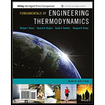
FUND OF ENG THERMODYN(LLF)+WILEYPLUS
9th Edition
ISBN: 9781119391777
Author: MORAN
Publisher: WILEY
expand_more
expand_more
format_list_bulleted
Question
error_outline
This textbook solution is under construction.
Students have asked these similar questions
De Moivre’s Theorem
hand-written solutions only, please.
Determine the shear flow qqq for the given profile when the shear forces acting at the torsional center are Qy=30Q_y = 30Qy=30 kN and Qz=20Q_z = 20Qz=20 kN. Also, calculate qmaxq_{\max}qmax and τmax\tau_{\max}τmax.
Given:Iy=10.5×10⁶I_y = 10.5 \times 10^6Iy=10.5×106 mm4^44,Iz=20.8×10⁶I_z = 20.8 \times 10^6Iz=20.8×106 mm4^44,Iyz=6×10⁶I_{yz} = 6 \times 10^6Iyz=6×106 mm4^44.
Additional parameters:αy=0.5714\alpha_y = 0.5714αy=0.5714,αz=0.2885\alpha_z = 0.2885αz=0.2885,γ=1.1974\gamma = 1.1974γ=1.1974.
(Check hint: τmax\tau_{\max}τmax should be approximately 30 MPa.)
Knowledge Booster
Similar questions
- hand-written solutions only, please.arrow_forwardIn the bending of a U-profile beam, the load path passes through the torsional center C, causing a moment of 25 kNm at the cross-section under consideration. Additionally, the beam is subjected to an axial tensile force of 100 kN at the centroid. Determine the maximum absolute normal stress.(Check hint: approximately 350 MPa, but where?)arrow_forward### Make an introduction to a report of a rocket study project, in the OpenRocket software, where the project consists of the simulation of single-stage and two-stage rockets, estimating the values of the exhaust velocities of the engines used, as well as obtaining the graphs of "altitude", "mass ratio x t", "thrust x t" and "ψ × t".arrow_forward
- A 6305 ball bearing is subjected to a steady 5000-N radial load and a 2000-N thrust load and uses a very clean lubricant throughout its life. If the inner race angular velocity is 500 rpm find The equivalent radial load the L10 life and the L50 lifearrow_forwardWhere on the below beam is the Maxiumum Slope likely to occur? C A; Атят Barrow_forwardWhat is the moment of Inertia of this body? What is Ixx, Iyy, and Izzarrow_forward
- i need the The shaft is supported by a smooth thrust bearing at AA and a smooth journal bearing at BB. Draw the shear diagram for the shaft. Follow the sign convention.arrow_forward4- In the system shown in the figure, the water velocity in the 12 in. diameter pipe is 8 ft/s. Determine the gage reading at position 1. Elevation 170 ft 1 Elevation 200 ft | 8 ft, 6-in.-diameter, 150 ft, 12-in.-diameter, f = 0.020 f = 0.020 A B Hints: the minor losses should consider the contraction loss at A and the expansion loss at B.arrow_forwardWhat is the moment of Inertia of this body? What is Ixx, Iyy, and Izzarrow_forward
- Consider a glass window (Hight = 1.2 m, Width = 2 m). The room thatfaces the window are maintained at 25 o C. The average temperature ofthe inner surface of the window is 5 o C. Calculate the total heat transferrate from through the window a) IdenCfy what type(s) of convecCon is important (circle one). • external forced (Chapter 7)• internal forced (Chapter 8)• natural convecCon (Chapter 9)• boiling and condensaCon (Chapter 10)b) IdenCfy the necessary equaCon(s) needed to solve the problem. c) IdenCfy important fluid properCes you need to solve the problem. d) Calculate the total heat transferred.arrow_forwardWater is condensing on a square plate (0.5 m x 0.5 m) placed verCcally. If the desired rate ofcondensaCon is 0.016 kJ/s, determine the necessary surface temperature of the plate at atmosphericpressure. Assume the film temperature of 90 o C for evaluaCon of fluid properCes of water and thesurface temperature of 80 o C for the evaluaCon of modified latent heat of vaporizaConarrow_forwardWater at 20 o C enters the 4 cm-diameter, 14 m-long tube at a rate of 0.8 kg/s. The surfacetemperature of the pipe is maintained at 165 o Cby condensing geothermal stream at the shellside of the heat exchanger. Use water properCesat 85 o C for all calculaCons.(a) Show that the water flow is turbulent and thermally fully developed. (b) EsCmate the heat transfer coefficient for convecCve heat transfer from the pipe to the water. For a fully developed turbulent flow within the smooth pipe, the Nu number can becalculated from the following equaCon:(c) Calculate the exit temperature of the water. (d) Share your opinion on whether the use of water properties at 85°C is appropriate. Yes or No because:arrow_forward
arrow_back_ios
SEE MORE QUESTIONS
arrow_forward_ios
Recommended textbooks for you
 Elements Of ElectromagneticsMechanical EngineeringISBN:9780190698614Author:Sadiku, Matthew N. O.Publisher:Oxford University Press
 Mechanics of Materials (10th Edition)Mechanical EngineeringISBN:9780134319650Author:Russell C. HibbelerPublisher:PEARSON
 Thermodynamics: An Engineering ApproachMechanical EngineeringISBN:9781259822674Author:Yunus A. Cengel Dr., Michael A. BolesPublisher:McGraw-Hill Education
 Control Systems EngineeringMechanical EngineeringISBN:9781118170519Author:Norman S. NisePublisher:WILEY
 Mechanics of Materials (MindTap Course List)Mechanical EngineeringISBN:9781337093347Author:Barry J. Goodno, James M. GerePublisher:Cengage Learning
 Engineering Mechanics: StaticsMechanical EngineeringISBN:9781118807330Author:James L. Meriam, L. G. Kraige, J. N. BoltonPublisher:WILEY

Elements Of Electromagnetics
Mechanical Engineering
ISBN:9780190698614
Author:Sadiku, Matthew N. O.
Publisher:Oxford University Press

Mechanics of Materials (10th Edition)
Mechanical Engineering
ISBN:9780134319650
Author:Russell C. Hibbeler
Publisher:PEARSON

Thermodynamics: An Engineering Approach
Mechanical Engineering
ISBN:9781259822674
Author:Yunus A. Cengel Dr., Michael A. Boles
Publisher:McGraw-Hill Education

Control Systems Engineering
Mechanical Engineering
ISBN:9781118170519
Author:Norman S. Nise
Publisher:WILEY

Mechanics of Materials (MindTap Course List)
Mechanical Engineering
ISBN:9781337093347
Author:Barry J. Goodno, James M. Gere
Publisher:Cengage Learning

Engineering Mechanics: Statics
Mechanical Engineering
ISBN:9781118807330
Author:James L. Meriam, L. G. Kraige, J. N. Bolton
Publisher:WILEY