
EBK SYSTEM DYNAMICS
3rd Edition
ISBN: 9780100254961
Author: Palm
Publisher: YUZU
expand_more
expand_more
format_list_bulleted
Concept explainers
Videos
Textbook Question
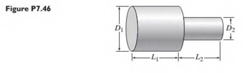
Chapter 7, Problem 7.46P
The copper shaft shown in Figure P7.46 consists of two cylinders w ith the following dimensions: — 10 mm, L2=5 mm, Dj = 2 mm, and D2= 1.5 mm. The shaft is insulated around its circumference so that heat transfer occurs only in the axial direction, (a) Compute the thermal resistance of each section of the shaft and of the total shaft. Use the follow ing value for the conductivity of copper: k = 400 W/m • °C. (b) Compute the heat flow rate in the axial direction if the temperature difference across the endpoints of the shaft is 30°C.
Expert Solution & Answer
Want to see the full answer?
Check out a sample textbook solution
Students have asked these similar questions
Problem (17): water flowing in an open channel of a rectangular cross-section with width (b) transitions from a
mild slope to a steep slope (i.e., from subcritical to supercritical flow) with normal water depths of (y₁) and
(y2), respectively.
Given the values of y₁ [m], y₂ [m], and b [m], calculate the discharge in the channel (Q) in [Lit/s].
Givens:
y1 = 4.112 m
y2 =
0.387 m
b = 0.942 m
Answers:
( 1 ) 1880.186 lit/s
( 2 ) 4042.945 lit/s
( 3 ) 2553.11 lit/s
( 4 ) 3130.448 lit/s
Problem (14): A pump is being used to lift water from an underground
tank through a pipe of diameter (d) at discharge (Q). The total head
loss until the pump entrance can be calculated as (h₁ = K[V²/2g]), h
where (V) is the flow velocity in the pipe. The elevation difference
between the pump and tank surface is (h).
Given the values of h [cm], d [cm], and K [-], calculate the maximum
discharge Q [Lit/s] beyond which cavitation would take place at the
pump entrance. Assume Turbulent flow conditions.
Givens:
h = 120.31 cm
d = 14.455 cm
K = 8.976
Q
Answers:
(1) 94.917 lit/s
(2) 49.048 lit/s
( 3 ) 80.722 lit/s
68.588 lit/s
4
Problem (13): A pump is being used to lift water from the bottom
tank to the top tank in a galvanized iron pipe at a discharge (Q).
The length and diameter of the pipe section from the bottom tank
to the pump are (L₁) and (d₁), respectively. The length and
diameter of the pipe section from the pump to the top tank are
(L2) and (d2), respectively.
Given the values of Q [L/s], L₁ [m], d₁ [m], L₂ [m], d₂ [m],
calculate total head loss due to friction (i.e., major loss) in the
pipe (hmajor-loss) in [cm].
Givens:
L₁,d₁
Pump
L₂,d2
오
0.533 lit/s
L1 =
6920.729 m
d1 =
1.065 m
L2 =
70.946 m
d2
0.072 m
Answers:
(1)
3.069 cm
(2) 3.914 cm
( 3 ) 2.519 cm
( 4 ) 1.855 cm
TABLE 8.1
Equivalent Roughness for New Pipes
Pipe
Riveted steel
Concrete
Wood stave
Cast iron
Galvanized iron
Equivalent Roughness, &
Feet
Millimeters
0.003-0.03 0.9-9.0
0.001-0.01 0.3-3.0
0.0006-0.003 0.18-0.9
0.00085
0.26
0.0005
0.15
0.045
0.000005
0.0015
0.0 (smooth) 0.0 (smooth)
Commercial steel or wrought iron 0.00015
Drawn…
Chapter 7 Solutions
EBK SYSTEM DYNAMICS
Ch. 7 - Prob. 7.1PCh. 7 - Refer to the water storage and supply system shown...Ch. 7 - Prob. 7.3PCh. 7 - In Figure P7.4 the piston of area A is connected...Ch. 7 - Refer to Figure 7.1.4a. and suppose that p\ — p2=...Ch. 7 - Pure water flows into a mixing tank of volume V =...Ch. 7 - Consider the mixing tank treated in Problem 7.6....Ch. 7 - Derive the expression for the fluid capacitance of...Ch. 7 - Prob. 7.9PCh. 7 - Prob. 7.10P
Ch. 7 - 7.11 Derive the expression for the capacitance of...Ch. 7 - Air flows in a certain cylindrical pipe 1 m long...Ch. 7 - Derive the expression for the linearized...Ch. 7 - Consider the cylindrical container treated in...Ch. 7 - A certain tank has a bottom area A = 20 m2. The...Ch. 7 - A certain tank has a circular bottom area A = 20...Ch. 7 - The water inflow rate to a certain tank was kept...Ch. 7 - Prob. 7.18PCh. 7 - Prob. 7.19PCh. 7 - In the liquid level system shown in Figure P7.20,...Ch. 7 - The water height in a certain tank was measured at...Ch. 7 - Derive the model for the system shown in Figure...Ch. 7 - (a) Develop a model of the two liquid heights in...Ch. 7 - Prob. 7.24PCh. 7 - Design a piston-type damper using an oil with a...Ch. 7 - Prob. 7.26PCh. 7 - 7.27 An electric motor is sometimes used to move...Ch. 7 - Prob. 7.28PCh. 7 - Prob. 7.29PCh. 7 - Figure P7.3O shows an example of a hydraulic...Ch. 7 - Prob. 7.31PCh. 7 - Prob. 7.32PCh. 7 - Prob. 7.33PCh. 7 - Prob. 7.34PCh. 7 - Prob. 7.35PCh. 7 - Prob. 7.36PCh. 7 - Prob. 7.37PCh. 7 - (a) Determine the capacitance of a spherical tank...Ch. 7 - Obtain the dynamic model of the liquid height It...Ch. 7 - Prob. 7.40PCh. 7 - Prob. 7.41PCh. 7 - Prob. 7.42PCh. 7 - Prob. 7.43PCh. 7 - Prob. 7.44PCh. 7 - Prob. 7.45PCh. 7 - The copper shaft shown in Figure P7.46 consists of...Ch. 7 - A certain radiator wall is made of copper with a...Ch. 7 - A particular house wall consists of three layers...Ch. 7 - A certain wall section is composed of a 12 in. by...Ch. 7 - Prob. 7.50PCh. 7 - Prob. 7.51PCh. 7 - A steel tank filled with water has a volume of...Ch. 7 - Prob. 7.53PCh. 7 - Prob. 7.54PCh. 7 - Prob. 7.55P
Knowledge Booster


Learn more about
Need a deep-dive on the concept behind this application? Look no further. Learn more about this topic, mechanical-engineering and related others by exploring similar questions and additional content below.Similar questions
- The flow rate is 12.275 Liters/s and the diameter is 6.266 cm.arrow_forwardAn experimental setup is being built to study the flow in a large water main (i.e., a large pipe). The water main is expected to convey a discharge (Qp). The experimental tube will be built at a length scale of 1/20 of the actual water main. After building the experimental setup, the pressure drop per unit length in the model tube (APm/Lm) is measured. Problem (20): Given the value of APm/Lm [kPa/m], and assuming pressure coefficient similitude, calculate the drop in the pressure per unit length of the water main (APP/Lp) in [Pa/m]. Givens: AP M/L m = 590.637 kPa/m meen Answers: ( 1 ) 59.369 Pa/m ( 2 ) 73.83 Pa/m (3) 95.443 Pa/m ( 4 ) 44.444 Pa/m *******arrow_forwardFind the reaction force in y if Ain = 0.169 m^2, Aout = 0.143 m^2, p_in = 0.552 atm, Q = 0.367 m^3/s, α = 31.72 degrees. The pipe is flat on the ground so do not factor in weight of the pipe and fluid.arrow_forward
- Find the reaction force in x if Ain = 0.301 m^2, Aout = 0.177 m^2, p_in = 1.338 atm, Q = 0.669 m^3/s, and α = 37.183 degreesarrow_forwardProblem 5: Three-Force Equilibrium A structural connection at point O is in equilibrium under the action of three forces. • • . Member A applies a force of 9 kN vertically upward along the y-axis. Member B applies an unknown force F at the angle shown. Member C applies an unknown force T along its length at an angle shown. Determine the magnitudes of forces F and T required for equilibrium, assuming 0 = 90° y 9 kN Aarrow_forwardProblem 19: Determine the force in members HG, HE, and DE of the truss, and state if the members are in tension or compression. 4 ft K J I H G B C D E F -3 ft -3 ft 3 ft 3 ft 3 ft- 1500 lb 1500 lb 1500 lb 1500 lb 1500 lbarrow_forward
- Problem 14: Determine the reactions at the pin A, and the tension in cord. Neglect the thickness of the beam. F1=26kN F2 13 12 80° -2m 3marrow_forwardProblem 22: Determine the force in members GF, FC, and CD of the bridge truss and state if the members are in tension or compression. F 15 ft B D -40 ft 40 ft -40 ft 40 ft- 5 k 10 k 15 k 30 ft Earrow_forwardProblem 20: Determine the force in members BC, HC, and HG. After the truss is sectioned use a single equation of equilibrium for the calculation of each force. State if the members are in tension or compression. 5 kN 4 kN 4 kN 3 kN 2 kN B D E F 3 m -5 m- -5 m- 5 m 5 m-arrow_forward
- An experimental setup is being built to study the flow in a large water main (i.e., a large pipe). The water main is expected to convey a discharge (Qp). The experimental tube will be built at a length scale of 1/20 of the actual water main. After building the experimental setup, the pressure drop per unit length in the model tube (APm/Lm) is measured. Problem (19): Given the value of Qp [m³/s], and assuming Reynolds number similitude between the water main and experimental tube, calculate the flow rate in the model tube (Qm) in [lit/s]. = 30.015 m^3/sarrow_forwardProblem 11: The lamp has a weight of 15 lb and is supported by the six cords connected together as shown. Determine the tension in each cord and the angle 0 for equilibrium. Cord BC is horizontal. E 30° B 60° Aarrow_forwardProblem 10: If the bucket weighs 50 lb, determine the tension developed in each of the wires. B $30° 5 E D 130°arrow_forward
arrow_back_ios
SEE MORE QUESTIONS
arrow_forward_ios
Recommended textbooks for you
 Principles of Heat Transfer (Activate Learning wi...Mechanical EngineeringISBN:9781305387102Author:Kreith, Frank; Manglik, Raj M.Publisher:Cengage Learning
Principles of Heat Transfer (Activate Learning wi...
Mechanical Engineering
ISBN:9781305387102
Author:Kreith, Frank; Manglik, Raj M.
Publisher:Cengage Learning
Understanding Conduction and the Heat Equation; Author: The Efficient Engineer;https://www.youtube.com/watch?v=6jQsLAqrZGQ;License: Standard youtube license