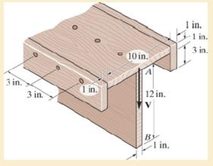
The beam is fabricated from four boards nailed together as shown. Determine the shear force each nail along the sides C and the top D must resist if the nails are uniformly spaced at s=3 in. The beam is subjected to a shear of V=4.5 kip.

The shear force
The shear force
Answer to Problem 7.1RP
The shear force
The shear force
Explanation of Solution
Given information:
The shear force is
The uniform nail spacing is 3 in.
Calculation:
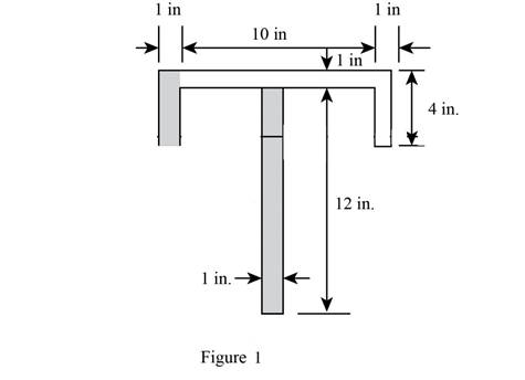
Sketch the diagram of the T section as shown in Figure 1.

Refer Figure 1,
The area of the beam is the sum of area of three rectangles 1, 2, and 3.
The dimensions of rectangle 1 as width
The dimensions of rectangle 2 as width
The dimensions of rectangle 2 as width
Find the value of area section 1 as shown below:
Substitute 10 in. for
Find the value of area section 2 as shown below:
Substitute 4 in. for
Find the value of area section 3 as shown below:
Substitute 12 in. for
Calculate the centroid of
Here,
Substitute
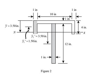
Sketch the diagram of

Calculate the moment of inertia of the beam (I) as follows:
Refer to Figure 2:
The value of
The value of
The value of
Substitute 10 in. for
Calculate the first moment area
Here,
Refer to Figure 2.
The value of
Substitute
Calculate the first moment area
Here,
Refer to Figure 2.
The value of
Substitute
Show the formula for shear flow
Here, V is the shear force, I is the moment of inertia, and
Substitute
Show the formula for shear flow
Here, V is the shear force, I is the moment of inertia, and
Substitute
Calculate the shear force
Here, s is the spacing and
Substitute
Hence, the shear force
Calculate the shear force
Here, s is the spacing and
Substitute
Hence, the shear force
Want to see more full solutions like this?
Chapter 7 Solutions
Mechanics of Materials (Custom)
- ased on the corresponding mass flow rates (and NOT the original volumetric flow rates) determine: a) The mass flow rate of the mixed air (i.e., the combination of the two flows) leaving the chamber in kg/s. b) The temperature of the mixed air leaving the chamber. Please use PyscPro software for solving this question. Notes: For part (a), you will first need to find the density or specific volume for each state (density = 1/specific volume). The units the 'v' and 'a' are intended as subscripts: · kgv = kg_v = kgv = kilogram(s) [vapour] kga = kg_a =kga = kilogram(s) [air]arrow_forwardThe answers to this question s wasn't properly given, I need expert handwritten solutionsarrow_forwardI need expert handwritten solutions to this onlyarrow_forward
- Two large tanks, each holding 100 L of liquid, are interconnected by pipes, with the liquid flowing from tank A into tank B at a rate of 3 L/min and from B into A at a rate of 1 L/min (see Figure Q1). The liquid inside each tank is kept well stirred. A brine solution with a concentration of 0.2 kg/L of salt flows into tank A at a rate of 6 L/min. The diluted solution flows out of the system from tank A at 4 L/min and from tank B at 2 L/min. If, initially, tank A contains pure water and tank B contains 20 kg of salt. A 6 L/min 0.2 kg/L x(t) 100 L 4 L/min x(0) = 0 kg 3 L/min B y(t) 100 L y(0) = 20 kg 2 L/min 1 L/min Figure Q1 - Mixing problem for interconnected tanks Determine the mass of salt in each tank at time t > 0: Analytically (hand calculations)arrow_forwardTwo springs and two masses are attached in a straight vertical line as shown in Figure Q3. The system is set in motion by holding the mass m₂ at its equilibrium position and pushing the mass m₁ downwards of its equilibrium position a distance 2 m and then releasing both masses. if m₁ = m₂ = 1 kg, k₁ = 3 N/m and k₂ = 2 N/m. www.m k₁ = 3 (y₁ = 0). m₁ = 1 k2=2 (y₂ = 0) |m₂ = 1 Y2 y 2 System in static equilibrium (Net change in spring length =32-31) System in motion Figure Q3 - Coupled mass-spring system Determine the equations of motion y₁(t) and y₂(t) for the two masses m₁ and m₂ respectively: Analytically (hand calculations)arrow_forward100 As a spring is heated, its spring constant decreases. Suppose the spring is heated and then cooled so that the spring constant at time t is k(t) = t sin N/m. If the mass-spring system has mass m = 2 kg and a damping constant b = 1 N-sec/m with initial conditions x(0) = 6 m and x'(0) = -5 m/sec and it is subjected to the harmonic external force f(t) = 100 cos 3t N. Find at least the first four nonzero terms in a power series expansion about t = 0, i.e. Maclaurin series expansion, for the displacement: Analytically (hand calculations)arrow_forward
- this is answer to a vibrations question. in the last part it states an assumption of x2, im not sure where this assumption comes from. an answer would be greatly appreciatedarrow_forwardPlease answer with the sketches.arrow_forwardThe beam is made of elastic perfectly plastic material. Determine the shape factor for the cross section of the beam (Figure Q3). [Take σy = 250 MPa, yNA = 110.94 mm, I = 78.08 x 106 mm²] y 25 mm 75 mm I 25 mm 200 mm 25 mm 125 Figure Q3arrow_forward
- A beam of the cross section shown in Figure Q3 is made of a steel that is assumed to be elastic- perfectectly plastic material with E = 200 GPa and σy = 240 MPa. Determine: i. The shape factor of the cross section ii. The bending moment at which the plastic zones at the top and bottom of the bar are 30 mm thick. 15 mm 30 mm 15 mm 30 mm 30 mm 30 mmarrow_forwardA torque of magnitude T = 12 kNm is applied to the end of a tank containing compressed air under a pressure of 8 MPa (Figure Q1). The tank has a 180 mm inner diameter and a 12 mm wall thickness. As a result of several tensile tests, it has been found that tensile yeild strength is σy = 250 MPa for thr grade of steel used. Determine the factor of safety with respect to yeild, using: (a) The maximum shearing stress theory (b) The maximum distortion energy theory T Figure Q1arrow_forwardAn external pressure of 12 MPa is applied to a closed-end thick cylinder of internal diameter 150 mm and external diameter 300 mm. If the maximum hoop stress on the inner surface of the cylinder is limited to 30 MPa: (a) What maximum internal pressure can be applied to the cylinder? (b) Sketch the variation of hoop and radial stresses across the cylinder wall. (c) What will be the change in the outside diameter when the above pressure is applied? [Take E = 207 GPa and v = 0.29]arrow_forward
 Elements Of ElectromagneticsMechanical EngineeringISBN:9780190698614Author:Sadiku, Matthew N. O.Publisher:Oxford University Press
 Mechanics of Materials (10th Edition)Mechanical EngineeringISBN:9780134319650Author:Russell C. HibbelerPublisher:PEARSON
 Thermodynamics: An Engineering ApproachMechanical EngineeringISBN:9781259822674Author:Yunus A. Cengel Dr., Michael A. BolesPublisher:McGraw-Hill Education
 Control Systems EngineeringMechanical EngineeringISBN:9781118170519Author:Norman S. NisePublisher:WILEY
 Mechanics of Materials (MindTap Course List)Mechanical EngineeringISBN:9781337093347Author:Barry J. Goodno, James M. GerePublisher:Cengage Learning
 Engineering Mechanics: StaticsMechanical EngineeringISBN:9781118807330Author:James L. Meriam, L. G. Kraige, J. N. BoltonPublisher:WILEY


