
EBK FOUNDATION DESIGN
3rd Edition
ISBN: 9780133424478
Author: CODUTO
Publisher: YUZU
expand_more
expand_more
format_list_bulleted
Textbook Question
Chapter 7, Problem 7.1QPP
List the three types of bearing capacity failures and explain the differences between them.
Expert Solution & Answer
To determine
The list of three types of bearing capacity failures and differences between them.
Explanation of Solution
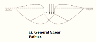
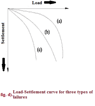
Three types of bearing capacity failures are:
- General shear failure.
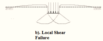
- Local shear failure.
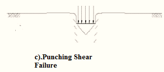
- Punching shear failure.
The differences between them are explained in tabular form below:
| Serial Number | General shear failure | Local shear failure | Punching shear failure |
| 1. | The continuous, well-defined failure surface | Not well-defined failure surface, | Failure surface is not well defined, no bulging of ground surface adjacent to the foundation |
| 2. | Sudden failure as shown in the load settlement curve.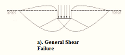 | Not a sudden failure. | Not a sudden failure, failure occurs gradually as depicted in the load-settlement curve. |
| 3. | Dense and stiff clay, incompressible soil | Relatively loose and soft soil | Lose and soft soil, highly compressible soil |
| 4. | Considerable settlement | Lage settlement occurs | |
| 5. | Bulging of failure surfaces at ground occurs | Slight bulging of soil around footing is observed | Shearing in vertical direction around the edge of the footing |
| 3. | Tilting of footing occurs | No tilting | No tilting |
| 7. | Relative density | Relative density | Relative density |
Want to see more full solutions like this?
Subscribe now to access step-by-step solutions to millions of textbook problems written by subject matter experts!
schedule07:16
Students have asked these similar questions
A sample of Achilles saturated with water has a mass of 1710 g. After heating in an oven, a constant mass of 1815 g is obtained. The density of solid Achilles seeds is 2.78 g/cm3. We are asked to calculate:
a) The water content and void ratio
b) The porosity and specific gravity of the clayey soil
c) The wet density of the clayey soil, the corresponding dry density and dry density
8. A prestressed concrete beam is subjected to the
following stress distributions:
Pi is the initial prestressing force, Pe is the effective
prestressing force, M, is the bending moment due to self-
weight, Ma and M, are the dead load and live load bending
moment, respectively.
The concrete has the following properties: fr = 6000 psi
and fri = 4200 psi
+250 -85 -2500
+550
Pe+ Mo+Ma+Mi
P alone
P₁+ Mo
-2450 -3500
Stress at midspan
+210
+250
P, alone
Pe alone
-2500 -3500
Stress at ends
Using Table 22.1, evaluate whether the stresses at the center of the span and the end of the span comply with the
permissible stress limits. The beam is classified as U-class.
Provide justifications for each condition listed in the table.
Note: Calculated stresses are to be taken from the above diagram, and permissible stresses are to be calculated
using Table 22.1.
Compressive stresses
immediately after transfer
Tensile stresses
immediately after transfer
Compressive stresses
under sustained and total…
10. A short column is subjected to an eccentric loading. The axial load P =
1000 kips and the eccentricity e = 12 in. The material strengths are fy = 60 ksi
and f = 6000 psi. The Young's modulus of steel is 29000 ksi.
(a) Fill in the blanks in the interaction diagram shown below.
(2pts each, 10pt total)
Po
Pn
(1)
failure range
H
3"
30"
Ast 6 No. 10 bars
=
P
22"
I
e
H
3"
(4) e =
e small
Load
path for
given e
Radial lines show constant (2)
eb
(3)
e large
failure range
Mn
(5) e=
Mo
(b) Compute the balanced failure point, i.e., P and Mb.
Chapter 7 Solutions
EBK FOUNDATION DESIGN
Ch. 7 - List the three types of bearing capacity failures...Ch. 7 - A 1.2 m square, 0.4 m deep spread footing is...Ch. 7 - A 5 ft wide, 8 ft long, 2 ft deep spread footing...Ch. 7 - A column carrying a vertical downward unfactored...Ch. 7 - A column carrying a vertical downward ultimate...Ch. 7 - A 120 ft diameter cylindrical tank with an empty...Ch. 7 - A 1.5 m wide, 2.5 m long, 0.5 m deep spread...Ch. 7 - A 5 ft wide, 8 ft long, 2 ft deep spread footing...Ch. 7 - A bearing wall carries a total unfactored load 220...Ch. 7 - After the footing in Problem 7.9 was built, the...
Ch. 7 - A bearing wall carries a factored ultimate...Ch. 7 - A 5 ft wide, 8 ft long, 3 ft deep footing supports...Ch. 7 - Prob. 7.13QPPCh. 7 - A spread footing supported on a sandy soil has...Ch. 7 - A certain column carries a vertical downward load...Ch. 7 - A building column carries a factored ultimate...Ch. 7 - A 3 ft square footing is founded at a depth of 2.5...Ch. 7 - A building column carries factored ultimate loads...Ch. 7 - Develop a spread sheet to compute allowable total...Ch. 7 - A certain column carries a vertical downward load...Ch. 7 - Repeat Problem 7.20 using LRFD assuming the...Ch. 7 - Conduct a bearing capacity analysis on the Fargo...Ch. 7 - Three columns, A, B, and C, are collinear, 500 mm...Ch. 7 - Two columns, A and B, are to be built 6 ft 0 in...Ch. 7 - In May 1970, a 70 ft tall, 20 ft diameter concrete...
Additional Engineering Textbook Solutions
Find more solutions based on key concepts
Explain how each of the following types of integrity constraints is enforced in the SQL CREATE TABLE commands: ...
Modern Database Management
In Exercises 41 through 46, identify the errors. Dim9WAsDouble9W=2*9WIstoutput.Items.Add(9W)
Introduction To Programming Using Visual Basic (11th Edition)
2-1 List the five types of measurements that form the
basis of traditional ptane surveying-
Elementary Surveying: An Introduction To Geomatics (15th Edition)
Use the following tables for your answers to questions 3.7 through 3.51 : PET_OWNER (OwnerID, OwnerLasst Name, ...
Database Concepts (8th Edition)
Why must the number of teeth on the cutter be known when calculating milling machine table feed, in in./min?
Degarmo's Materials And Processes In Manufacturing
Suppose a class has a field named description. The fields data type is String. How would you indicate the field...
Starting Out with Programming Logic and Design (5th Edition) (What's New in Computer Science)
Knowledge Booster

Similar questions
- No chatgpt plsarrow_forward11. The prestressed T beam shown below is pretensioned using low relaxation stress-relieved Grade 270 strands. The steel area Aps = 2.5 in². The tensile strength is fpu = 270 ksi, and the concrete compressive strength is fr = 6000 psi. (a) Calculate the nominal moment strength Mn with hr = 6 in. 22" 15" T hf (b) Since this beam is a T-beam, the nominal moment strength M₁ increases with a thicker hf. However, M, stops increasing if he reaches a value. Determine the minimum thickness hy that can achieve the maximum nominal moment strength Mr. Also, calculate the corresponding maximum nominal moment strength Mn with the computed hf.arrow_forward10. A short column is subjected to an eccentric loading. The axial load P = 1000 kips and the eccentricity e = 12 in. The material strengths are fy = 60 ksi and f = 6000 psi. The Young's modulus of steel is 29000 ksi. (a) Fill in the blanks in the interaction diagram shown below. 30" Ast 6 No. 10 bars = Pn (1) Po (4) e = e small Load path for given e failure range Radial lines show constant (2) eb (3) e large failure range Mn (5) e= Mo (b) Compute the balanced failure point, i.e., P and Mb. H 3" P 22" I e H 3"arrow_forward
- 10. A short column is subjected to an eccentric loading. The axial load P = 1000 kips and the eccentricity e = 12 in. The material strengths are fy = 60 ksi and f = 6000 psi. The Young's modulus of steel is 29000 ksi. (a) Fill in the blanks in the interaction diagram shown below. 30" Ast 6 No. 10 bars = Pn (1) Po (4) e = e small Load path for given e failure range Radial lines show constant (2) eb (3) e large failure range Mn (5) e= Mo (b) Compute the balanced failure point, i.e., P and Mb. H 3" P 22" I e H 3"arrow_forward7. Match the given strand profiles with the corresponding loading conditions for a prestressed concrete (PSC) beam. Strand profile (b) (d) (c) (a) Ꮎ Load on a beamarrow_forward4. For serviceability considerations, the effective moment of inertia (Ie) is calculated using the following formula: le 1 - 1cr ((2/3) Mcr) Ma 2 - وا ≥ Note that the upper bound was previously set as Iut in the earlier ACI equation. (a) Arrange the following moment of inertia values in ascending order (from smallest to largest): le, Ier, Ig and lut (b) Mer is the cracking moment. Choose the cross-section that should be used to compute Mcr. NA. h 5. Identify and circle the figure that represents the scenario in which the torsional effect is permitted to be reduced according to the ACI code provisions. (3 pts) mt mi B (b)arrow_forward
- I will rate, thanksarrow_forward. 9. A reinforced concrete beam is subjected to V/ = 40 kips and Tu/ = 12 ft kips at the critical section. Given conditions: ⚫ Longitudinal reinforcements use No. 8 grade 60 steel with an effective depth d = 20 in. For shear capacity, V = 18 kips and V₂ = 22 kips • For transverse reinforcements, use No. 3 bars with grade 60. • The effective torsional area of A. = 150 in². • Crack angle = 45° ⚫ The minimum stirrup spacing is Smin = 4" and the maximum stirrup spacing is Smax = Find the required stirrup spacing at the critical section. 8".arrow_forward3. The beam shown on the right uses three No. 8 bars made of Grade 60 steel as longitudinal reinforcement. The allowable maximum center-to-center spacing of the longitudinal rebars has been determined to be 10 inches. Now assume that Grade 80 steel will be used instead. Determine whether the beam satisfies the rebar spacing requirements according to the ACI Code. Additional assumptions: • Estimate fs = fy • 20" Clear cover: ? 12" Clear side cover: 1.5" The clear cover depth cc and the clear side cover remain unchanged, regardless of the change in material.arrow_forward
- 6. For the slender columns shown below: a) Determine the effective buckling length factor (k) for each column. b) Circle the column with the largest buckling capacity, assuming all columns have the same length (f) and the same flexural rigidity (E+I) k = (a) (b) (c) (d)arrow_forward5. Identify and circle the figure that represents the scenario in which the torsional effect is permitted to be reduced according to the ACI code provisions. mi (a) V7+ B (b)arrow_forward5. Identify and circle the figure that represents the scenario in which the torsional effect is permitted to be reduced according to the ACI code provisions. (3 pts) mi (a) V7+ B (b)arrow_forward
arrow_back_ios
SEE MORE QUESTIONS
arrow_forward_ios
Recommended textbooks for you
 Principles of Foundation Engineering (MindTap Cou...Civil EngineeringISBN:9781305081550Author:Braja M. DasPublisher:Cengage Learning
 Construction Materials, Methods and Techniques (M...Civil EngineeringISBN:9781305086272Author:William P. Spence, Eva KultermannPublisher:Cengage Learning
 Fundamentals of Geotechnical Engineering (MindTap...Civil EngineeringISBN:9781305635180Author:Braja M. Das, Nagaratnam SivakuganPublisher:Cengage Learning
 Principles of Geotechnical Engineering (MindTap C...Civil EngineeringISBN:9781305970939Author:Braja M. Das, Khaled SobhanPublisher:Cengage Learning
 Principles of Foundation Engineering (MindTap Cou...Civil EngineeringISBN:9781337705028Author:Braja M. Das, Nagaratnam SivakuganPublisher:Cengage Learning
 Traffic and Highway EngineeringCivil EngineeringISBN:9781305156241Author:Garber, Nicholas J.Publisher:Cengage Learning
Principles of Foundation Engineering (MindTap Cou...
Civil Engineering
ISBN:9781305081550
Author:Braja M. Das
Publisher:Cengage Learning
Construction Materials, Methods and Techniques (M...
Civil Engineering
ISBN:9781305086272
Author:William P. Spence, Eva Kultermann
Publisher:Cengage Learning
Fundamentals of Geotechnical Engineering (MindTap...
Civil Engineering
ISBN:9781305635180
Author:Braja M. Das, Nagaratnam Sivakugan
Publisher:Cengage Learning
Principles of Geotechnical Engineering (MindTap C...
Civil Engineering
ISBN:9781305970939
Author:Braja M. Das, Khaled Sobhan
Publisher:Cengage Learning
Principles of Foundation Engineering (MindTap Cou...
Civil Engineering
ISBN:9781337705028
Author:Braja M. Das, Nagaratnam Sivakugan
Publisher:Cengage Learning
Traffic and Highway Engineering
Civil Engineering
ISBN:9781305156241
Author:Garber, Nicholas J.
Publisher:Cengage Learning