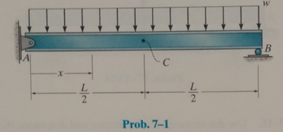
Determine the equation of the elastic curve using the coordinate x, and specify the slope at point A and the deflection at point C. EI is constant.

The equation of elastic curve using the coordinate
Answer to Problem 7.1P
The equation of elastic curve is shown below.
The slope at point A is,
The deflection at C is,
Explanation of Solution
Calculation:
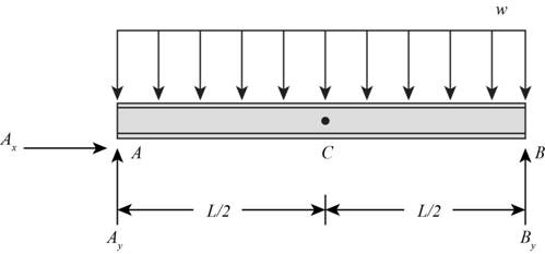
The following figure shows the free body diagram of the beam.

Figure-(1)
Write the Equilibrium Equation for the sum of horizontal forces.
Here, horizontal reaction at A is
Write the Equilibrium Equation for the sum of vertical forces.
Here, vertical reactions at point A and B are
Due to symmetry of the beam, the reactions at point A and B will be half of the total load acting on the beam.
Consider the section x-x at distance
Write the Equation for sum of moment about x-x.
Write the differential equation of the elastic curve as shown below.
Substitute
Here,
Calculate the value of
Apply the boundary conditions at the support points.
At
Substitute
Calculate the value of
At
Substitute
Calculate the slope equation.
Substitute
Calculate the deflection equation.
Substitute
Calculate the slope at A.
Substitute
Calculate the deflection at C.
Substitute
Conclusion:
The equation of elastic curve is shown below.
The slope at point A is,
The deflection at C is,
Want to see more full solutions like this?
Chapter 7 Solutions
Structural Analysis (10th Edition)
Additional Engineering Textbook Solutions
Starting Out with Programming Logic and Design (5th Edition) (What's New in Computer Science)
Mechanics of Materials (10th Edition)
Electric Circuits. (11th Edition)
Modern Database Management
Java: An Introduction to Problem Solving and Programming (8th Edition)
Computer Science: An Overview (13th Edition) (What's New in Computer Science)
- For an reinforced concrete two-way slab shown in figure under the load (P). (the slab continuous over all edges - all sides are fixed), Determine (By using yield line theory): A- Draw the Yield line Pattern B- Determine the moment m C- Find The required flexural steel to resist the loads causing the slab to collapse if P = 200 KN, f=28 MPa, fy = 420 MPa d = 120 mm. Use 10 mm bars. Draw the yield line and (Qmin = 0.002) 2m solve PO 6 m 3 m -8 marrow_forwardFind the internal torques for segments AB, BC, and CD (in N-m) by drawing the internal torque diagram, the maximum torsional shear on the shaft in MPa, and the relative rotation of section A with respect to section D in degrees.arrow_forwardFor an reinforced concrete two-way slab shown in figure under the load (P). (the slab continuous over all edges - all sides are fixed), Solve by using equilibrium method A- Draw the Yield line Pattern B- Determine the moment m C- Find The required flexural steel to resist the loads causing the slab to collapse if P = 200 kN, f=28 MPa, fy = 420 MPa d = 120 mm. Use 10 mm bars. (Pmin = 0.002) 2 m 6 m -8 m 3 marrow_forward
- A double-T simply supported concrete beam its cross section is shown in Figure, is prestressed with 2 tendons each 400 mm². Determine the allowable service load. Use span 12 m, fse = 1300 MPa, fe = 40 MPa, y = 25 kN/m³. = 1200 mm >09 *100* As = 400 +100+ As = 400 400 1400+arrow_forwardA double-T simply supported concrete beam its cross section is shown in Figure, is prestressed with 2 tendons each 400 mm². Determine the allowable service load. Use span 12 m, fse = 1300 MPa, fc = 40 MPa, y = 25 kN/m³. = 1200 mm >09< *100* As = 400 +100+ As = 400 400 1400+arrow_forwardA prestressed simply supported 15 m span beam with rectangular box section is post-tensioned by straight high tensile steel wires as shown in Figure. The prestressing wires are placed at the center line of the flanges and initially stressed to 850 N/mm². The beam is required to carry a uniformly distributed superimposed load of 4.5 kN/m in addition to its weight. If the concrete stresses are not to exceed 17 MPa in compression and 1 MPa in tension at service stage, calculate the range of the total prestressing wires area required. Ignore prestressing force losses in your answer. (Ye kN/m³). = 24 2As 400 As 80 80; 750arrow_forward
- A simply supported rectangular prestressed concrete beam, of span 13 m and its cross section as shown in figure, is carrying a live load equals to 30 kN/m in addition to its weight, compute the following stresses and compare it with ACI allowable stress: a) Bottom fiber stress at support in initial stage. b) Top fiber stress at mid span in final stage. Use y = 24 kN/m³, As = 600 mm², initial stress of the prestressed steel = 1200 MPa, total losses is 20%, fci = 22 MPa, and fo' = 28 MPa 800 mm 3 As 400 mm As 340 mm 340 mmarrow_forwardA study of the properties of metal plate-connected trusses used for roof support yielded the following observations on axial stiffness index (kips/in.) for plate lengths 4, 6, 8, 10, and 12 in: 4: 320.2 409.5 311.0 326.5 316.8 349.8 309.7 6: 401.1 347.2 361.0 404.5 331.0 348.9 381.7 8: 395.4 366.2 351.0 357.1 409.9 367.3 382.0 10: 356.7 452.9 461.4 433.1 410.6 384.2 362.6 12: 415.4 441.8 419.9 410.7 473.4 441.2 465.8 USE SALT Does variation in plate length have any effect on true average axial stiffness? State the relevant hypotheses using analysis of variance. O Ho M1 M2 M3 = μ4=μ5 Ha all five μ's are unequal Ho: M1 M2 M3 #44 #μ5 Ha all five μ's are equal Ho: M₁ μ2 43 #44 #μ5 H₁: at least two μ,'s are equal O Ho M1 M2 M3 = μ4=μ5 Ha at least two μ's are unequal Test the relevant hypotheses using analysis of variance with a = 0.01. Display your results in an ANOVA table. (Round your answers to two decimal places.) Degrees of Sum of Mean Source Squares Squares f freedom Treatments Error…arrow_forward1-Define a cartesion system 2 identify the structure's supports and the type of structure (2D) or 3D 3-If the structure has more than one element dismember the structure and draw free body diagram(show all actions and reactions) on each element independently 4- Determine the type of suports 5- show the unkown supports reactions with any assumed direction but you cannot change the assumed force direction once you dicede 6-In a common joint, you can dicide on the force direction in one element, however, in the other one you need to follow the Newton'ns 3rd law and shoe the opposite direction 7- if you have multiple actions forces in the system, find force components for each foce independently use Sin/Cos/Tan functions to find forces components in two perpendicular directions 8- Add forces in each direction since they are paralled forces Rx=fx Ry=fy Rz= fyarrow_forward
- Physical properties of six flame-retardant fabric samples were investigated in an article. Use the accompanying data and a 0.05 significance level to determine whether a linear relationship exists between stiffness x (mg-cm) and thickness y (mm). x y 8.08 24.33 12.39 6.99 23.97 35.64 0.25 0.68 0.30 0.28 0.82 0.57 State the appropriate null and alternative hypotheses. ○ Ho: p = 0 H₂: pO ○ Hop = 0 Hap #0 Compute the value of the sample correlation coefficient, r. Round your answer to four decimal places. Calculate the test statistic and determine the P-value. (Round your test statistic to two decimal places and your P-value to three decimal places.) P-value = State the conclusion in the problem context. O Fail to reject Ho. The data indicates that the population correlation coefficient differs from 0. Fail to reject Ho. The data does not indicate that the population correlation coefficient differs from 0. Reject Ho. The data indicates that the population correlation coefficient differs…arrow_forward1-Define a cartesion system 2 identify the structure's supports and the type of structure (2D) or 3D 3-If the structure has more than one element dismember the structure and draw free body diagram(show all actions and reactions) on each element independently 4- Determine the type of suports 5- show the unkown supports reactions with any assumed direction but you cannot change the assumed force direction once you dicede 6-In a common joint, you can dicide on the force direction in one element, however, in the other one you need to follow the Newton'ns 3rd law and shoe the opposite direction 7- if you have multiple actions forces in the system, find force components for each foce independently use Sin/Cos/Tan functions to find forces components in two perpendicular directions 8- Add forces in each direction since they are paralled forces Rx=fx Ry=fy Rz= fyarrow_forward- - A study reports data on the effects of the drug tamoxifen on change in the level of cortisol-binding globulin (CBG) of patients during treatment. With age = x and ACBG = y, summary values are n = 26, Ex, = 1613, Σ(x, x)² = 3756.96, Ey, = 281.9, (y, v)² = 465.34, and Exy, = 16,709. (a) Compute a 90% CI for the true correlation coefficient p. (Round your answers to four decimal places.) (b) Test Ho: p =-0.5 versus Ha: p< -0.5 at level 0.05. Calculate the test statistic and determine the P-value. (Round your test statistic to two decimal places and your P-value to four decimal places.) P-value = State the conclusion in the problem context. Fail to reject Ho. There is evidence that p < -0.5. Reject Ho. There is no evidence that p < -0.5. Reject Ho. There is evidence that p < -0.5. Fail to reject Ho. There is no evidence that p < -0.5. (c) In a regression analysis of y on x, what proportion of variation in change of cortisol-binding globulin level could be explained by variation in…arrow_forward
 Principles of Foundation Engineering (MindTap Cou...Civil EngineeringISBN:9781305081550Author:Braja M. DasPublisher:Cengage Learning
 Steel Design (Activate Learning with these NEW ti...Civil EngineeringISBN:9781337094740Author:Segui, William T.Publisher:Cengage Learning
 Residential Construction Academy: House Wiring (M...Civil EngineeringISBN:9781285852225Author:Gregory W FletcherPublisher:Cengage Learning
 Materials Science And Engineering PropertiesCivil EngineeringISBN:9781111988609Author:Charles GilmorePublisher:Cengage Learning
 Engineering Fundamentals: An Introduction to Engi...Civil EngineeringISBN:9781305084766Author:Saeed MoaveniPublisher:Cengage Learning


