
Concept explainers
(a)
Find the quantity of water flowing through the sample per hour.
(a)
Answer to Problem 7.1CTP
The quantity of water flowing through the sample per hour is
Explanation of Solution
Given information:
The length of each soil layer
The total length of the soil layer H is 600 mm.
The diameter of the cylindrical tube d is 150 mm.
The constant head difference
The porosity of the soil layer I
The porosity of the soil layer II
The porosity of the soil layer III
The hydraulic conductivity of soil layer I
The hydraulic conductivity of soil layer II
The hydraulic conductivity of soil layer III
Calculation:
Determine the hydraulic conductivity in the vertical direction using the relation.
Substitute 600 mm for H, 200 mm for
Determine the hydraulic gradient using the relation.
Here, L is the total length of the soil layer.
Substitute 470 mm for
Determine the area of the cylindrical tube using the relation.
Substitute 150 mm for d.
Determine the rate of seepage per unit length of the dam using the relation.
Substitute
Therefore, the quantity of water flowing through the sample per hour is
(b)
Find the elevation head (Z), pressure head
(b)
Answer to Problem 7.1CTP
The elevation head (
The pressure head
The total head
The elevation head (
The pressure head
The total head
The elevation head (
The pressure head
The total head
The elevation head (
The pressure head
The total head
Explanation of Solution
Given information:
The length of each soil layer
The total length of the soil layer H is 600 mm.
The diameter of the cylindrical tube d is 150 mm.
The constant head difference
The porosity of the soil layer I
The porosity of the soil layer II
The porosity of the soil layer III
The hydraulic conductivity of soil layer I
The hydraulic conductivity of soil layer II
The hydraulic conductivity of soil layer III
Calculation:
Determine the elevation head (
Here,
Substitute 220 mm for
Therefore, the elevation head (
Determine the pressure head
Substitute 470 mm for
Therefore, the pressure head
Determine the total head
Substitute 690 mm for
Therefore, the total head
Determine the elevation head (
Substitute 220 mm for
Therefore, the elevation head (
Determine the value of
Substitute
Determine the total head
Substitute 470 mm for
Therefore, the total head
Determine the pressure head
Substitute 436.3 mm for
Therefore, the pressure head
Determine the elevation head
Substitute 220 mm for
Therefore, the elevation head (
Determine the value of
Substitute
Determine the total head
Substitute 436.3 mm for
The total head
Determine the pressure head
Substitute 432.3 mm for
Therefore, The pressure head
Determine the elevation head
Substitute 220 mm for
Therefore, the elevation head (
Determine the value of
Substitute
Determine the total head
Substitute 432.3 mm for
Therefore, the total head
Determine the pressure head
Substitute 432.3 mm for
Therefore, the pressure head
(c)
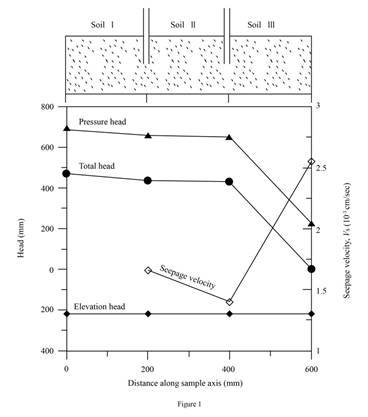
Plot the variation of the elevation head, pressure head, and the total head with the horizontal distance along the sample axis (X–X).
(c)
Explanation of Solution
Given information:
The length of each soil layer
The total length of the soil layer H is 600 mm.
The diameter of the cylindrical tube d is 150 mm.
The constant head difference
The porosity of the soil layer I
The porosity of the soil layer II
The porosity of the soil layer III
The hydraulic conductivity of soil layer I
The hydraulic conductivity of soil layer II
The hydraulic conductivity of soil layer III
Calculation:
Refer Part b)
Draw the graph between the elevation head pressure head, and the total head with the horizontal distance along the sample axis (X–X) as in Figure (1).
(d)
Plot the variation of the discharge velocity and the seepage velocity along the sample axis (X–X).
(d)
Explanation of Solution
Given information:
The length of each soil layer
The total length of the soil layer H is 600 mm.
The diameter of the cylindrical tube d is 150 mm.
The constant head difference
The porosity of the soil layer I
The porosity of the soil layer II
The porosity of the soil layer III
The hydraulic conductivity of soil layer I
The hydraulic conductivity of soil layer II
The hydraulic conductivity of soil layer III
Calculation:
Determine the discharge velocity v using the relation.
Substitute
Determine the seepage velocity of soil I using the relation.
Here,
Substitute 0.000843 cm/sec for v and 0.5 for
Determine the seepage velocity of soil II using the relation.
Here,
Substitute 0.000843 cm/sec for v and 0.6 for
Determine the seepage velocity of soil III using the relation.
Here,
Substitute 0.000843 cm/sec for v and 0.33 for
Draw graph of variation of the discharge velocity and the seepage velocity along the sample axis (X–X).
Refer Figure (1) in Part (c).
(e)
Find the height of the vertical columns of water inside piezometers A and B installed on the sample axis.
(e)
Answer to Problem 7.1CTP
The height of the vertical columns of water at point A is
The height of the vertical columns of water at point B is
Explanation of Solution
Given information:
The length of each soil layer
The total length of the soil layer H is 600 mm.
The diameter of the cylindrical tube d is 150 mm.
The constant head difference
The porosity of the soil layer I
The porosity of the soil layer II
The porosity of the soil layer III
The hydraulic conductivity of soil layer I
The hydraulic conductivity of soil layer II
The hydraulic conductivity of soil layer III
Calculation:
The height of water column is equal to the Piezometric or pressure head at a point.
Determine the height of water in point A.
Substitute 656.3 mm for
Therefore, the height of the vertical columns of water at point A is
Determine the height of water in point B.
Substitute 652.3 mm for
Therefore, the height of the vertical columns of water at point B is
Want to see more full solutions like this?
Chapter 7 Solutions
PRINCIPLES OF GEOTECH.ENGINEERING >LL+M


- Determine the bending moment at support A for the beam shown using the slope-deflection method. Use the sign convention defined in the chapter. a. 232.9 k-ft b. -182.1 k-ft c. 182.1 k-ft d. -232.9 k-ftarrow_forwardWhat is the shear and normal stresses of Point J and Point K?arrow_forwardWhat are the states of stress (magnitude and tension/compression of the normal stresses and shear stress) at Point J and Point K?arrow_forward
- Consider, M people (aka pax) who want to travel by car from O to D. They all start working at D at Q (e.g., Q-8am). If a person departs at time t, assume the time needed to go from O to D is given by c(t)=A+Bx(t), where x(t) is the flow of people departing at time t [car/unit of time]. In addition, a is the penalty for being early at work (E(t) is how early the person arrived when departing at time t), and ẞ is the penalty for being late at work (L(t) is how late the person arrived when departing at time t). Assume 0 < a < 1 < ß. Further assume the departure time choice problem under the equilibrium conditions. Prove that the arrival time of people who depart when most of the M people start their trips is equal to Q.arrow_forwarda. A b. A 3. Sketch normal depth, critical depth and the water surface profile. Assume at A and B the water is flowing at normal depth. Label and Identify all curves (i.e., M1, S2, etc.) Yn > Ye Уп Ye Уп> Ус yarrow_forward2. Design a trapezoidal ditch to carry Q = 1000 cfs. The ditch will be a lined channel, gravel bottom with sides shown below on a slope of S = 0.009. The side slopes of the 20-ft wide ditch will be 1 vertical to 3 horizontal. a) Determine the normal depth of flow (yn) using the Normal value for Manning's n. b) If freeboard requirements are 25% of the normal depth, how deep should the ditch be constructed? c) Classify the slope. T b Уп Z 1 Yn + FBarrow_forwardP15.45 WP A stainless steel pipe (Figure P15.45) with an outside diameter of 2.375 in. and a wall thickness of 0.109 in. is subjected to a bending moment M = 50 lb ft and an internal pressure of 180 psi. Determine the absolute maximum shear stress on the outer surface of the pipe. M FIGURE P15.45 Marrow_forward10.72 What power must the pump supply to the system to pump the oil from the lower reservoir to the upper reservoir at a rate of 0.3 m³/s? Sketch the HGL and the EGL for the system. p=940 kg/m³ v = 10-5 m²/s Elevation 100 m Elevation 112 m L= 150 m Oil Steel pipe D = 30 cm Problem 10.72arrow_forwardL / 83° 28° $75°E M 202° Q2: The scanning process was completed from point J to point N. The direction of the straight line was LM and the angles of deviation are shown in the figure below. Find the direction of the remaining sides? Narrow_forwardQ3: The scanning process was completed from point F to point G. The direction of the line Fl and the angles of deviation and interior are shown in the figure below. Find the direction of the remaining sides? Azimn = 60° F 52° 52° 72° R= 572.958/D ° T-R tan(A/2) • LC 2R sin (A/2) • E-R (sec(A/2)-1) • M-R (1-cos (A/2)) L= 10 A/D •C=2R sin(2D/2) • d=Dc/10 c' 2R sin (d/2) • Y= √√R2-X2-K • K= R2- K=R-M G H معادلات :مفيدةarrow_forwardPlease write me Background Reviews;arrow_forwardQ1/ The specific gravity of the soil is 1.41 percentage of water content by weight at field capacity and wilting point are 15% and 7% respectively calculate the equivalent moisture content as equivalent depth for 1.2m root zone : 1. at permanent wilting point 2. at field capacity 3. for ready available waterarrow_forwardarrow_back_iosSEE MORE QUESTIONSarrow_forward_ios
 Principles of Geotechnical Engineering (MindTap C...Civil EngineeringISBN:9781305970939Author:Braja M. Das, Khaled SobhanPublisher:Cengage Learning
 Fundamentals of Geotechnical Engineering (MindTap...Civil EngineeringISBN:9781305635180Author:Braja M. Das, Nagaratnam SivakuganPublisher:Cengage Learning
 Principles of Foundation Engineering (MindTap Cou...Civil EngineeringISBN:9781337705028Author:Braja M. Das, Nagaratnam SivakuganPublisher:Cengage Learning