
Concept explainers
Videos
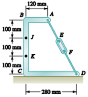
Knowing that the turnbuckle has been tightened until the tension in wire AD is 850 N, determine the internal forces at the point indicated: 7.154 Point J.
The internal forces.
Answer to Problem 7.154RP
The internal forces are
Explanation of Solution
The free body diagram is given in figure 1.
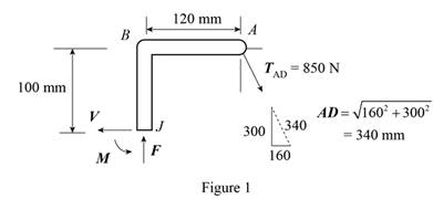
From the diagram, net force along horizontal and vertical directions is zero. Write the equilibrium condition for the forces.
Here,
The net moment at point J is zero. Therefore, the equilibrium condition is,
Here, M is the moment of internal force.
Conclusion:
Substitute 280 mm for CD, 120 mm for AB, 300 mm for BC and 850 N for
Substitute 280 mm for CD, 120 mm for AB, 300 mm for BC and 850 N for
Substitute 400 N for V, 750 N for F, 100 mm for BJ and 120 mm for AB in the expression for M.
Therefore, the internal forces are
Want to see more full solutions like this?
Chapter 7 Solutions
Vector Mechanics for Engineers: Statics and Dynamics


- For the following MATLAB code, I need to answer a few questions. Can you identify the curves as elliptic functions? Which curves reflect the sn, cn, and dn functions?From the curves, determine the maximum amplitudes and the period corresponding toeach angular velocity component. clc; clear all; I = [500; 125; 425]; w = [0.2; 0.1; 0.2]; rev = 0:0.01:10; C = eye(3); % Using ode45 to integrate the KDE and DDE options = odeset('RelTol',1e-9,'AbsTol',1e-9); result = ode45(@K_DDE, rev, [w; I; C(:)], options); v = result.x; % Extracting information from the ode45 solver w = result.y(1:3, :); C_ode = reshape(result.y(7:end, :), [3,3,length(v)]); plot(v, w) xlabel('rev') ylabel('w (rad/s)') legend('w1', 'w2', 'w3') % Functions function dwCdt = K_DDE(~, w_IC) % Extracting the initial condtions to a variable w = w_IC(1:3); I = w_IC(4:6); C = reshape(w_IC(7:end), [3, 3]); I1 = I(1); I2 = I(2); I3 = I(3); K1 = -(I3-I2)/I1; K2 = -(I1-I3)/I2; K3 = -(I2-I1)/I3; %…arrow_forwardplease show a drawing/image and explain how to properly do the question. thanksarrow_forwardFor the four-bar- linkage shown in the following figure. BC=68mm, CD=100mm, AD=120mm. Determine the range of AB to make it a crank-rocker mechanism. B Darrow_forward
- all of those 4 fi 1)Draw kinematic diagram: 2)DOF: 3)type/name of mechanism 4)evolution:arrow_forward7.4 Impeller viscometer The rheology of a Penicillium chrysogenum broth is examined using an impeller viscometer. The density of the cell suspension is approximately 1000 kg m³. Samples of broth are stirred under laminar conditions using a Rushton turbine of diameter 4 cm in a glass beaker of diameter 15 cm. The average shear rate generated by the impeller is greater than the stirrer speed by a factor of about 10.2. When the stirrer shaft is attached to a device for measuring torque and rotational speed, the following results are recorded. Stirrer speed (s¹) Torque (Nm) 0.185 3.57 × 10⁻⁶ 0.163 3.45 × 10⁻⁶ 0.126 3.31 x 10⁻⁶ 0.111 3.20×10⁻⁶ Can the rheology be described using a power-law model? If so, evaluate K and n.arrow_forward(read image)arrow_forward
- (read image) Answer Providedarrow_forwardThis is part B Part A's question and answer was find moment of inertia (Ix = 3.90×10^5) and radius of gyration (kx = 21.861) Determine the centroid ( x & y ) of the I-section, Calculate the moment of inertia of the section about itscentroidal x & y axes. How or why is this result different fromthe result of a previous problem?arrow_forwardDetermine by direct integration the moment of inertia of theshaded area of figure with respect to the y axis shownarrow_forward
- Consider the feedback controlled blending system shown below, which is designed to keep theoutlet concentration constant despite potential variations in the stream 1 composition. The density of all streamsis 920 kg/m3. At the nominal steady state, the flow rates of streams 1 and 2 are 950 and 425 kg/min,respectively, the liquid level in the tank is 1.3 m, the incoming mass fractions are x1 = 0.27, x2 = 0.54. Noticethe overflow line, indicating that the liquid level remains constant (i.e. any change in total inlet flow ratetranslates immediately to the same change in the outlet flow rate). You may assume the stream 1 flowrate andthe stream 2 composition are both constant. Use minutes as the time unit throughout this problem. Identify any controlled variable(s) (CVs), manipulated variable(s) (MVs),and disturbance variable(s) (DVs) in this problem. For each, explain how you know that’show it is classified.CVs: ___________, MVs: _____________, DVs: ______________ b) Draw a block diagram…arrow_forwardA heat transfer experiment is conducted on two identical spheres which are initially at the same temperature. The spheres are cooled by placing them in a channel. The fluid velocity in the channel is non-uniform, having a profile as shown. Which sphere cools off more rapidly? Explain. V 1arrow_forwardMy ID# 016948724 last 2 ID# 24 Last 3 ID# 724 Please help to find the correct answer for this problem using my ID# first write le line of action and then help me to find the forces {fx= , fy= mz= and for the last find the moment of inertial about the show x and y axes please show how to solve step by steparrow_forward
 Elements Of ElectromagneticsMechanical EngineeringISBN:9780190698614Author:Sadiku, Matthew N. O.Publisher:Oxford University Press
 Mechanics of Materials (10th Edition)Mechanical EngineeringISBN:9780134319650Author:Russell C. HibbelerPublisher:PEARSON
 Thermodynamics: An Engineering ApproachMechanical EngineeringISBN:9781259822674Author:Yunus A. Cengel Dr., Michael A. BolesPublisher:McGraw-Hill Education
 Control Systems EngineeringMechanical EngineeringISBN:9781118170519Author:Norman S. NisePublisher:WILEY
 Mechanics of Materials (MindTap Course List)Mechanical EngineeringISBN:9781337093347Author:Barry J. Goodno, James M. GerePublisher:Cengage Learning
 Engineering Mechanics: StaticsMechanical EngineeringISBN:9781118807330Author:James L. Meriam, L. G. Kraige, J. N. BoltonPublisher:WILEY