
Concept explainers
Videos
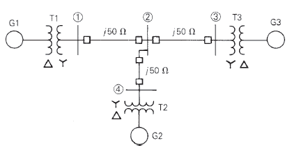
Equipment ratings for the four-bus power system shown in Figure 7.14 are as follows:
Generator G1: 500 MVA, 13.8 kV,
Generator G2: 750 MVA, 18 kV,
Generator G3: 1000 MVA, 20 kV,
Transformer T1: 500 MVA,
Transformer T2: 750 MVA,
Transformer T3: 1000Â MVA,
A three-phase short circuit occurs at bus 1, where the prefault voltage is 525 kV. Prefault load current is neglected. Draw the positive-sequence reactance diagram in per unit on a 1000-MVA, 20-kV base in the zone of generator G3. Determine (a) the Thévenin reactance in per unit at the fault, (b) the subtransient fault current in per unit and in kA rms, and (c) contributions to the fault current from generator G1 and from line 1-2.

Trending nowThis is a popular solution!

Chapter 7 Solutions
Power System Analysis and Design (MindTap Course List)


- 1. Choose all nodes that must be included, if any, to construct the supernode for Nodal analysis. OV1, V3 OV1, V2 ○ V2, V3 OV1, V2, V4 OV1, V2, V3 O V2, V3, V4 2. Write KCL equation (Nodal equation) at super-node. Write your expression in terms of node voltages V1, V2, V3 and V4 and of the form (G11 V1+G12 V2+G13 V3+G14 V4 = 11), then enter the corresponding values: At super-node KCL: 1/Q G11 1/0 G12 1/Ω G13 1/Q G14 A 3. Use the above equation, the circuit and and super-node inner expression to calculate V3 and then lo : V3= V 10 = R3 Vst + A V₁ + VS2 V₂ V3 w W R₁ R₂ R4 ww R5 V4 V$3arrow_forwardEnter the matrix values (numerical) to solve for voltages at nodes v1, and v2, for the circuit shown, using Nodal equations. In the matrix, row 1, and row 2, correspond to node v1, and node v2 current expressions, respectively. Let Is1=14, Is2=7, R₁=5, R₂-8, R3=2, and R4-5. [G11 G12] [Vi₁ The matrix values are shown here: = G21 G22 [V2] [41] [12] {Hint: As discussed in class and to avoid sign errors, assume nodal currents are locally defined at each node (leaving) and use node labeling as indicated in the circuit. } The relative tolerance for this problem is 5%. VI R2 ww Isl 12 NODE v1 G11 G12 RI 1/Q 1/0 A 4= NODE v2 G21- 1/Q G22 1/0 12 W A === www R3 R4 www Use Cramer's rule (matrix), substitution, or any other method to calculate the voltages: v1 = V v2= V Is2arrow_forwardOnly expert should attemptarrow_forward
- For the circuit shown below, let l₁ = 9, 1₂ = 14, 13= 12, R₁ = 3, R₂ = 8, and R3 = 5. Use nodal equations to determine V1, V2 and I, as follows: • Consider Node 1, obtain a nodal equation in terms of V₁ and V₂ voltages. Simplify your equation to the format 1V1 + b,V₂ = c, then enter the corresponding values of coefficients b₁ and c₁ 1. b₁ =( C₁ = • Now consider Node 2, obtain a second nodal equation in terms of V₁ and V2 voltages. Simplify your equation to the format -1V₁+b2V2=c2 then enter the corresponding values of coefficients b₂ and c₂ 2. (b₂ = value.) ,၄၇ = - 3. Use (1) and (2) to determine V₂ = 4. Determine V₁ 5. Determine | = i 12 V₁ R1 20 www R2 ww I The relative tolerance for this problem is 5%. R3 This is not a decimal or integer www i3arrow_forwardFor the circuit shown, let V1 = 19 V, Vs2 = 76 V, R₁ = 9, R2 = 9, and R3 = 7. Use Nodal analysis to determine the voltage V2 and the current lo, choose the closet values: V2- 4.788 10 = ○ 2.28 11.978 17.761 35.522 23.957 -9.146 8.32 10.173 A O-7.435 O-5.783 10.531 V sl ་ ་ ་ ན ་་་ ་ ་ ་ ་ ་ ་ ་ ་ +1 ww R₁ R₂ ww R3 Io +1 VS2arrow_forwardNO AI PLEASEarrow_forward
- NO AI PLEASEarrow_forwardProblem 4 Consider the following system. In the figure, y(t) denotes the displacement of the mass and u(t) denotes the force applied to the mass. b1 u(t) y(t) + b2 M 0000 0000 K1 K2 a) Find the differential equation model of the system. b) Find the state-space model for the system. Write x, A, B, C and D clearly in your answer.arrow_forwardNO AI PLEASEarrow_forward
- Not use ai pleasearrow_forwardShow workarrow_forwardProblem 1 (a) Suppose the Laplace transform of a causal signal x₁ (t) is given by S X₁(s) = 52 +2 Using the Laplace transform properties, find the Laplace transform of the following signal x2(t). x2(t) = e2t+1 x₁(t − 1) - tx₁(2t - 1) (b) Suppose an LTI system T whose impulse response is given by h(t) e 2t 1(t) t 1(t) +28(t) What is the transfer function of the system? (c) If the input x2 (t) is applied to the system T, what will be the output Y₂(s)? Note, you just need to provide Laplace transform of the output y₂(t). Simplification is not needed in any part of this question.arrow_forward
 Power System Analysis and Design (MindTap Course ...Electrical EngineeringISBN:9781305632134Author:J. Duncan Glover, Thomas Overbye, Mulukutla S. SarmaPublisher:Cengage Learning