
PEARSON ETEXT ENGINEERING MECH & STATS
15th Edition
ISBN: 9780137514724
Author: HIBBELER
Publisher: PEARSON
expand_more
expand_more
format_list_bulleted
Videos
Textbook Question
Chapter 7, Problem 5P
The pliers are used to grip the tube at B. If a force of 20 lb is applied to the handles, determine the internal shear force and moment a point C. Assume the jaws of the pliers exert only normal forces on the tube.
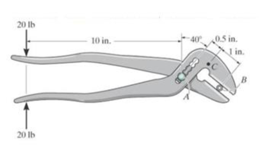
Prob. 7-5
Expert Solution & Answer
Want to see the full answer?
Check out a sample textbook solution
Students have asked these similar questions
(read image)
(read image)
(read me)
Chapter 7 Solutions
PEARSON ETEXT ENGINEERING MECH & STATS
Ch. 7 - Determine the normal force, shear force, and...Ch. 7 - Determine the normal force, shear force, and...Ch. 7 - Determine the normal force, shear force, and...Ch. 7 - Determine the normal force, shear force, and...Ch. 7 - Determine the normal force, shear force, and...Ch. 7 - Determine the normal force, shear force, and...Ch. 7 - Determine the shear force and moment at points C...Ch. 7 - The pliers are used to grip the tube at B. If a...Ch. 7 - Determine the distance a as a fraction of the...Ch. 7 - The cable will fail when subjected to a tension of...
Ch. 7 - Determine the distance a between the bearings in...Ch. 7 - The cantilevered rack is used to support each end...Ch. 7 - Rod AB is fixed to a smooth collar D, which slides...Ch. 7 - Prob. 22PCh. 7 - Determine the normal force, shear force, and...Ch. 7 - The distributed loading W = W0 sin , measured per...Ch. 7 - Solve Prob. 7-39 for = 120. Probs. 739/40Ch. 7 - Determine the x, y, z components of force and...Ch. 7 - Determine the x, y, z components of internal...Ch. 7 - Determine the shear and moment as a function of x,...Ch. 7 - Determine the shear and moment as a function of x,...Ch. 7 - Determine the shear and moment as a function of x,...Ch. 7 - Determine the shear and moment as a function of x,...Ch. 7 - Determine the shear and moment as a function of x,...Ch. 7 - Determine the shear and moment as a function of x,...Ch. 7 - Draw the shear and moment diagrams for the shaft...Ch. 7 - Draw the shear and moment diagrams for the beam...Ch. 7 - Draw the shear and moment diagrams for the beam...Ch. 7 - Draw the shear and moment diagrams for the...Ch. 7 - Draw the shear and moment diagrams of the beam (a)...Ch. 7 - If L = 9 m, the beam will fail when the maximum...Ch. 7 - Draw the shear and moment diagrams for the beam....Ch. 7 - Draw the shear and moment diagrams for the beam....Ch. 7 - The shaft is supported by a smooth thrust bearing...Ch. 7 - Draw the shear and moment diagrams for the beam....Ch. 7 - Prob. 58PCh. 7 - Prob. 59PCh. 7 - The shaft is supported by a smooth thrust bearing...Ch. 7 - Draw the shear and moment diagrams for the beam....Ch. 7 - Prob. 65PCh. 7 - Draw the shear and moment diagrams for the beam....Ch. 7 - Draw the shear and moment diagrams for the beam....Ch. 7 - Draw the shear and moment diagrams for the beam....Ch. 7 - Draw the shear and moment diagrams for the beam....Ch. 7 - Draw the shear and moment diagrams for the beam....Ch. 7 - Draw the shear and moment diagrams for the beam....Ch. 7 - Draw the shear and moment diagrams for the beam....Ch. 7 - Draw the shear and moment diagrams for the beam....Ch. 7 - Draw the shear and moment diagrams for the beam....Ch. 7 - Draw the shear and moment diagrams for the beam....Ch. 7 - Draw the shear and moment diagrams for the beam....Ch. 7 - Draw the shear and moment diagrams for the beam....Ch. 7 - Draw the shear and moment diagrams for the beam....Ch. 7 - The cable supports the three loads shown....Ch. 7 - Prob. 95PCh. 7 - Determine the tension in each segment of the cable...Ch. 7 - Prob. 97PCh. 7 - The cable supports the loading shown. Determine...Ch. 7 - The cable supports the three loads shown....Ch. 7 - The cable supports the three loads shown....Ch. 7 - Determine the maximum uniform loading w, measured...Ch. 7 - The cable is subjected to a uniform loading of w =...Ch. 7 - If x = 2 ft and the crate weighs 300 lb, which...Ch. 7 - If yB = 1.5 ft. determine the largest weight of...Ch. 7 - The cable supports a girder which weighs 850...Ch. 7 - If the pipe has a mass per unit length of 1500...Ch. 7 - Prob. 110PCh. 7 - The cable will break when the maximum tension...Ch. 7 - Prob. 2RPCh. 7 - Prob. 3RPCh. 7 - Prob. 4RPCh. 7 - Draw the shear and moment diagrams for the beam....Ch. 7 - A chain is suspended between points at the same...
Additional Engineering Textbook Solutions
Find more solutions based on key concepts
Computers process data under the control of sets of instructions called
Java How to Program, Early Objects (11th Edition) (Deitel: How to Program)
What is an uninitialized variable?
Starting Out with Programming Logic and Design (5th Edition) (What's New in Computer Science)
The solid steel shaft AC has a diameter of 25 mm and is supported by smooth bearings at D and E. It is coupled ...
Mechanics of Materials (10th Edition)
A byte is made up of eight a. CPUs b. addresses c. variables d. bits
Starting Out with Java: From Control Structures through Objects (7th Edition) (What's New in Computer Science)
This optional Google account security feature sends you a message with a code that you must enter, in addition ...
SURVEY OF OPERATING SYSTEMS
The ____________ is always transparent.
Web Development and Design Foundations with HTML5 (8th Edition)
Knowledge Booster


Learn more about
Need a deep-dive on the concept behind this application? Look no further. Learn more about this topic, mechanical-engineering and related others by exploring similar questions and additional content below.Similar questions
- (read me)arrow_forward(read image)arrow_forwardQu. 13 What are the indices for the Direction 2 indicated by vector in the following sketch? Qu. 14 Determine the indices for the direction A and B shown in the following cubic unit cell. please show all work step by step from material engineeringarrow_forward
- The thin-walled open cross section shown is transmitting torque 7. The angle of twist ₁ per unit length of each leg can be determined separately using the equation 01 = 3Ti GLIC 3 where G is the shear modulus, ₁ is the angle of twist per unit length, T is torque, and L is the length of the median line. In this case, i = 1, 2, 3, and T; represents the torque in leg i. Assuming that the angle of twist per unit length for each leg is the same, show that T= Lic³ and Tmaz = G01 Cmax Consider a steel section with Tallow = 12.40 kpsi. C1 2 mm L1 20 mm C2 3 mm L2 30 mm C3 2 mm L3 25 mm Determine the torque transmitted by each leg and the torque transmitted by the entire section. The torque transmitted by the first leg is | N-m. The torque transmitted by the second leg is N-m. The torque transmitted by the third leg is N-m. The torque transmitted by the entire section is N-m.arrow_forwardPlease help, make sure it's to box out and make it clear what answers go where...arrow_forwardThe cylinder floats in the water and oil to the level shown. Determine the weight of the cylinder. (rho)o=910 kg/m^3arrow_forward
arrow_back_ios
SEE MORE QUESTIONS
arrow_forward_ios
Recommended textbooks for you
 Elements Of ElectromagneticsMechanical EngineeringISBN:9780190698614Author:Sadiku, Matthew N. O.Publisher:Oxford University Press
 Mechanics of Materials (10th Edition)Mechanical EngineeringISBN:9780134319650Author:Russell C. HibbelerPublisher:PEARSON
 Thermodynamics: An Engineering ApproachMechanical EngineeringISBN:9781259822674Author:Yunus A. Cengel Dr., Michael A. BolesPublisher:McGraw-Hill Education
 Control Systems EngineeringMechanical EngineeringISBN:9781118170519Author:Norman S. NisePublisher:WILEY
 Mechanics of Materials (MindTap Course List)Mechanical EngineeringISBN:9781337093347Author:Barry J. Goodno, James M. GerePublisher:Cengage Learning
 Engineering Mechanics: StaticsMechanical EngineeringISBN:9781118807330Author:James L. Meriam, L. G. Kraige, J. N. BoltonPublisher:WILEY
Elements Of Electromagnetics
Mechanical Engineering
ISBN:9780190698614
Author:Sadiku, Matthew N. O.
Publisher:Oxford University Press
Mechanics of Materials (10th Edition)
Mechanical Engineering
ISBN:9780134319650
Author:Russell C. Hibbeler
Publisher:PEARSON
Thermodynamics: An Engineering Approach
Mechanical Engineering
ISBN:9781259822674
Author:Yunus A. Cengel Dr., Michael A. Boles
Publisher:McGraw-Hill Education
Control Systems Engineering
Mechanical Engineering
ISBN:9781118170519
Author:Norman S. Nise
Publisher:WILEY
Mechanics of Materials (MindTap Course List)
Mechanical Engineering
ISBN:9781337093347
Author:Barry J. Goodno, James M. Gere
Publisher:Cengage Learning
Engineering Mechanics: Statics
Mechanical Engineering
ISBN:9781118807330
Author:James L. Meriam, L. G. Kraige, J. N. Bolton
Publisher:WILEY
Mechanics of Materials Lecture: Beam Design; Author: UWMC Engineering;https://www.youtube.com/watch?v=-wVs5pvQPm4;License: Standard Youtube License