LogixPro PLC Lab Manual for Programmable Logic Controllers
5th Edition
ISBN: 9781259680847
Author: Frank D. Petruzella
Publisher: McGraw-Hill Education
expand_more
expand_more
format_list_bulleted
Textbook Question
Chapter 7, Problem 3P
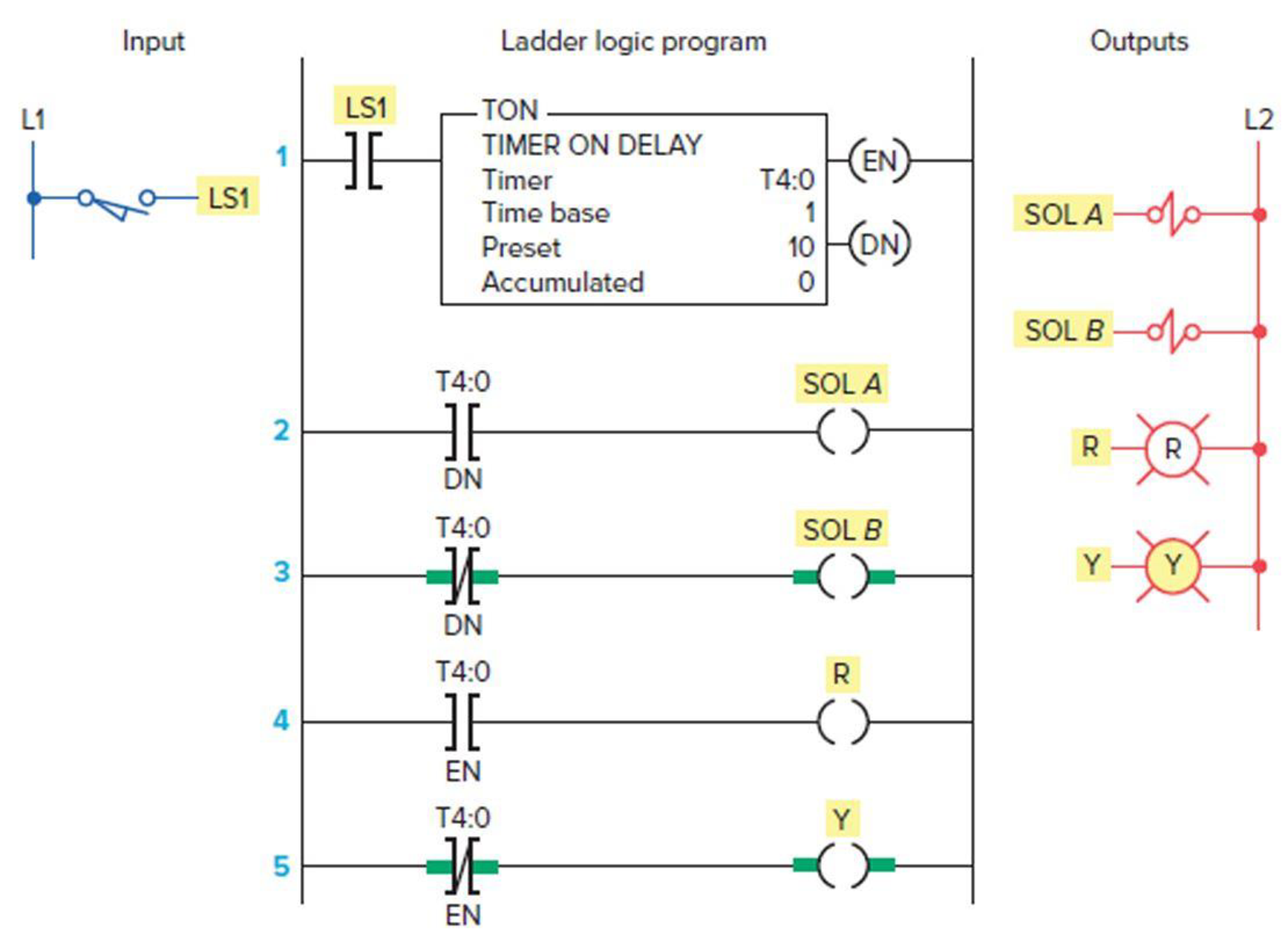
Study the ladder logic
- a. What type of timer has been programmed?
- b. What is the length of the time-delay period?
- c. What is the value of the accumulated time when power is first applied?
- d. When does the timer start timing?
- e. When does the timer stop timing and reset itself?
- f. When input LS1 is first closed, which rungs are true and which are false?
- g. When input LS1 is first closed, state the status (on or off) of each output.
- h. When the timer’s accumulated value equals the preset value, which rungs are true and which are false?
- i. When the timer’s accumulated value equals the preset value, state the status (on or off) of each output.
- j. Suppose that rung 1 is true for 5 s and then power is lost. What will the accumulated value of the counter be when power is restored?

Expert Solution & Answer
Want to see the full answer?
Check out a sample textbook solution
Students have asked these similar questions
4. |z + 5 - 5i| = 7
14.
dz,
C: |z❘
C: |z❘ = 0.6
ze² - 2iz
H
14.
dz,
C: |z❘
C: |z❘ = 0.6
ze² - 2iz
H
Chapter 7 Solutions
LogixPro PLC Lab Manual for Programmable Logic Controllers
Ch. 7 - Prob. 1RQCh. 7 - Prob. 2RQCh. 7 - Prob. 3RQCh. 7 - Prob. 4RQCh. 7 - a. What are the two methods commonly used to...Ch. 7 - Prob. 6RQCh. 7 - Prob. 7RQCh. 7 - Prob. 8RQCh. 7 - For a TOF timer: a. When is the enable bit of a...Ch. 7 - Explain what each of the following quantities...
Ch. 7 - State the method used to reset the accumulated...Ch. 7 - Study the ladder logic program in Figure 7-40 and...Ch. 7 - Study the ladder logic program in Figure 7-42, and...Ch. 7 - Prob. 6PCh. 7 - Prob. 7PCh. 7 - Prob. 8PCh. 7 - Prob. 9PCh. 7 - Prob. 10PCh. 7 - Prob. 11PCh. 7 - Prob. 13PCh. 7 - When the lights are turned off in a building, an...
Additional Engineering Textbook Solutions
Find more solutions based on key concepts
Which of the following are illegal variable names in Python, and why? x 99bottles july2009 theSalesFigureForFis...
Starting Out with Python (4th Edition)
This optional Google account security feature sends you a message with a code that you must enter, in addition ...
SURVEY OF OPERATING SYSTEMS
Why is the study of database technology important?
Database Concepts (8th Edition)
Assume a telephone signal travels through a cable at two-thirds the speed of light. How long does it take the s...
Electric Circuits. (11th Edition)
How are relationships between tables expressed in a relational database?
Modern Database Management
Comprehension Check 7-14
The power absorbed by a resistor can be given by P = I2R, where P is power in units of...
Thinking Like an Engineer: An Active Learning Approach (4th Edition)
Knowledge Booster
Similar questions
arrow_back_ios
SEE MORE QUESTIONS
arrow_forward_ios
Recommended textbooks for you
- Programming Logic & Design ComprehensiveComputer ScienceISBN:9781337669405Author:FARRELLPublisher:Cengage
 Systems ArchitectureComputer ScienceISBN:9781305080195Author:Stephen D. BurdPublisher:Cengage Learning
 A+ Guide to Hardware (Standalone Book) (MindTap C...Computer ScienceISBN:9781305266452Author:Jean AndrewsPublisher:Cengage Learning
  EBK JAVA PROGRAMMINGComputer ScienceISBN:9781305480537Author:FARRELLPublisher:CENGAGE LEARNING - CONSIGNMENT
 A+ Guide To It Technical SupportComputer ScienceISBN:9780357108291Author:ANDREWS, Jean.Publisher:Cengage,
 Operations Research : Applications and AlgorithmsComputer ScienceISBN:9780534380588Author:Wayne L. WinstonPublisher:Brooks Cole

Programming Logic & Design Comprehensive
Computer Science
ISBN:9781337669405
Author:FARRELL
Publisher:Cengage

Systems Architecture
Computer Science
ISBN:9781305080195
Author:Stephen D. Burd
Publisher:Cengage Learning

A+ Guide to Hardware (Standalone Book) (MindTap C...
Computer Science
ISBN:9781305266452
Author:Jean Andrews
Publisher:Cengage Learning

EBK JAVA PROGRAMMING
Computer Science
ISBN:9781305480537
Author:FARRELL
Publisher:CENGAGE LEARNING - CONSIGNMENT

A+ Guide To It Technical Support
Computer Science
ISBN:9780357108291
Author:ANDREWS, Jean.
Publisher:Cengage,

Operations Research : Applications and Algorithms
Computer Science
ISBN:9780534380588
Author:Wayne L. Winston
Publisher:Brooks Cole