
Concept explainers
Videos
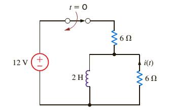
Use the differential equation approach to find i(t) for
The current
Answer to Problem 1P
Explanation of Solution
Given information:
Given circuit is shown below
Fig: Given circuit diagram
Calculation:
Although for -
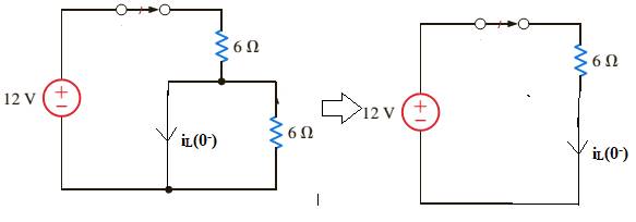
Fig: Circuit diagram for
Now, draw the circuit when switch is opened at t =0.
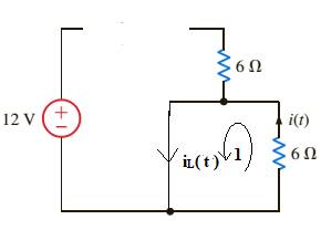
Fig: circuit diagram for
Apply KVL for loop 1
Standard from of solution of above equation is
Plugging
Therefore,
Now, from equation (1),
Want to see more full solutions like this?
Chapter 7 Solutions
Basic Engineering Circuit Analysis
Additional Engineering Textbook Solutions
Web Development and Design Foundations with HTML5 (8th Edition)
Starting Out with C++ from Control Structures to Objects (9th Edition)
Concepts Of Programming Languages
Computer Science: An Overview (13th Edition) (What's New in Computer Science)
Database Concepts (8th Edition)
Degarmo's Materials And Processes In Manufacturing


- Can you show how this answer was found:arrow_forwardQ1 [2 point] Perform 13+10 in the following Adder- Subtractor: A= |B= A3 B3 IB2 B1 A0 BO FAH FAH FAH FA M CO Q2 [2 point] Perform 13-10 in the following Adder- Subtractor: A= B= A3 B3 A2 B2 A1 B1 A0 BO A = = BC= AB FA FA FA FA M COarrow_forwardMatlab Homework (20ps) A BFSK signal is transmitted through a channel with AWGN. Generate similar BFSK received signal plots as shown on next page. (20 pts) BFSK for eb-1 and npower=0.01 with 500 samples BFSK for eb=1 and npower=0.1 with 500 samples 2.5 2.5 2 1.5 1 0.5 0 -0.5 -1 2 1.5 1 0.5 0 0.5 -1 -1.5 1.5 -1.5 -1 -0.5 0 0.5 1 1.5 2 2.5 -1.5 -1 -0.5 0 0.5 1 1.5 2 2.5arrow_forward
- Can you show how this answer was found?arrow_forward1. You are to design a 9-volt battery operated baseband PAM communication system that must last great than 10 years without replacing the batteries. The application requires a BER of <10^-4 and a data rate of 200bps. The channel can be modeled as AWGN with a noise power spectral density of 10^-9 W/Hz and a channel loss of 10 dB. (a) Estimate the required capacity of the batteries. (The battery life (hours) is equal to the battery volts times of the battery capacity (Amps* hours) divided by the total load (Watts)) and (b) Can you easily find this battery? If not, what would you suggest be done?arrow_forward3. You are on a design team tasked to design a system of remote sensors that use PAM. Here is what the team knows/assumptions: The remote sensor will use a single AA battery required to power the sensors. The system has a bandwidth of 2KHz and requires a data rate of 12 Kbps and a BER of less than 1*10^-4. The typical channel has maximum losses of 35 dB and a noise power spectral density is 10^-9 W/Hz. Your boss assigns you with the task of estimating how long the battery will last.arrow_forward
- 2. The noise power (in watts) measured in a baseband PAM communication channel is 230*10^-6 Watts. The transmitter output power is 600 mW and has a data rate of 300 Kbps. The channel bandwidth is 100 KHz with losses that can be modeled as 0.5dB/meter. The application requires a BER ofarrow_forwardQ27arrow_forwardQ25arrow_forwardarrow_back_iosSEE MORE QUESTIONSarrow_forward_ios
 Power System Analysis and Design (MindTap Course ...Electrical EngineeringISBN:9781305632134Author:J. Duncan Glover, Thomas Overbye, Mulukutla S. SarmaPublisher:Cengage Learning