
Mechanics of Materials
11th Edition
ISBN: 9780137605460
Author: Russell C. Hibbeler
Publisher: Pearson Education (US)
expand_more
expand_more
format_list_bulleted
Videos
Textbook Question
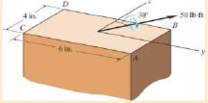
Chapter 6.5, Problem 15FP
Determine the maximum bending stress in the beam’s cross section.
Expert Solution & Answer
Want to see the full answer?
Check out a sample textbook solution
Students have asked these similar questions
70. Compute the number of cubic centimeters of iron required for the cast-iron plate
shown. The plate is 3.50 centimeters thick. Round the answer to the nearest cubic
centimeter.
50.0 cm
40.0 cm
Radius
150°
115.0 cm-
81.0 cm
Law of Sines
Solve the following problems using the Law of Sin
7. Find side x.
All dimensions are in inches.
-°-67°-37° 81°
x
Sin A
8.820
X
67°00'
32°00'
a
sin A
b
C
sin B
sin C
35. a. Determine B.
b. Determine side b.
c. Determine side c.
5.330 in.-
ZB
73°30'
Chapter 6 Solutions
Mechanics of Materials
Ch. 6.2 - and then draw the shear and moment diagrams for...Ch. 6.2 - In each case, express the shear and moment...Ch. 6.2 - In each case, express the shear and moment...Ch. 6.2 - In each case, express the shear and moment...Ch. 6.2 - In each case, draw the shear and moment diagrams...Ch. 6.2 - In each case, draw the shear and moment diagrams...Ch. 6.2 - In each case, draw the shear and moment diagrams...Ch. 6.2 - In each case, draw the shear and moment diagrams...Ch. 6.2 - Prob. 1PCh. 6.2 - Prob. 2P
Ch. 6.2 - Prob. 3PCh. 6.2 - Express the shear and moment in terms of x for 0 ...Ch. 6.2 - Express the internal shear and moment in the...Ch. 6.2 - Draw the shear and moment diagrams for the shaft....Ch. 6.2 - Determine the shear and moment as functions of x,...Ch. 6.2 - Determine the shear and moment as functions of x,...Ch. 6.2 - Determine the shear and moment as functions of x,...Ch. 6.2 - Determine the shear and moment in the double...Ch. 6.2 - Draw the shear and moment diagrams for the...Ch. 6.2 - Draw the shear and moment diagrams for the shaft....Ch. 6.2 - Draw the shear and moment diagrams for the...Ch. 6.2 - Draw the shear and moment diagrams for the...Ch. 6.2 - Draw the shear and moment diagrams for the...Ch. 6.2 - Prob. 16PCh. 6.2 - Draw the shear and moment diagrams for the simply...Ch. 6.2 - Prob. 19PCh. 6.2 - Draw the shear and moment diagrams for the beam.Ch. 6.2 - Draw the shear and moment diagrams for the...Ch. 6.2 - The 150-lb man sits in the center of the boat,...Ch. 6.2 - Prob. 24PCh. 6.2 - Draw the shear and moment diagrams for the beam.Ch. 6.2 - Prob. 26PCh. 6.2 - Draw the shear and moment diagrams for the beam....Ch. 6.2 - Prob. 29PCh. 6.2 - Prob. 30PCh. 6.2 - Prob. 31PCh. 6.2 - Prob. 34PCh. 6.2 - Prob. 35PCh. 6.2 - The beam is used to support a uniform load along...Ch. 6.2 - Prob. 39PCh. 6.2 - Prob. 42PCh. 6.2 - Prob. 43PCh. 6.2 - Prob. 44PCh. 6.2 - Prob. 45PCh. 6.2 - The truck is to be used to transport the concrete...Ch. 6.4 - If the beam is subjected to a bending moment of M...Ch. 6.4 - If the beam is subjected to a bending moment of M...Ch. 6.4 - If the beam is subjected to a bending moment of M...Ch. 6.4 - If the beam is subjected to a bending moment of M...Ch. 6.4 - If the beam is subjected to a bending moment of M...Ch. 6.4 - Determine the moment M that will produce a maximum...Ch. 6.4 - Determine the maximum tensile and compressive...Ch. 6.4 - The beam is constructed from four pieces of wood,...Ch. 6.4 - The beam is constructed from four pieces of wood,...Ch. 6.4 - The beam is made from three boards nailed together...Ch. 6.4 - The beam is made from three boards nailed together...Ch. 6.4 - Prob. 54PCh. 6.4 - The tubular shaft is supported by a smooth thrust...Ch. 6.4 - Prob. 57PCh. 6.4 - If the beam is subjected to an internal moment or...Ch. 6.4 - If the beam is made of material having an...Ch. 6.4 - Prob. 60PCh. 6.4 - Prob. 61PCh. 6.4 - The beam is subjected to a moment of M = 40 kN m....Ch. 6.4 - The steel shaft has a diameter of 2 in. It is...Ch. 6.4 - Determine the dimension a of a beam having a...Ch. 6.4 - A shaft is made of a polymer having an elliptical...Ch. 6.4 - Solve Prob. 6-65 if the moment M = 50 N m is...Ch. 6.4 - Prob. 67PCh. 6.4 - If M=4kipft , determine the resultant force the...Ch. 6.4 - The strut on the utility pole supports the cable...Ch. 6.4 - The pin is used to connect the three links...Ch. 6.4 - Prob. 75PCh. 6.4 - A timber beam has a cross section which is...Ch. 6.4 - If the beam is subjected to an internal moment of...Ch. 6.4 - If the allowable tensile and compressive stress...Ch. 6.4 - If the beam is subjected to an internal moment of...Ch. 6.4 - Prob. 80PCh. 6.4 - Prob. 81PCh. 6.4 - Prob. 82PCh. 6.4 - Prob. 83PCh. 6.4 - If the intensity of the load w=15kN/m , determine...Ch. 6.4 - Prob. 85PCh. 6.4 - Determine the absolute maximum bending stress in...Ch. 6.4 - Prob. 87PCh. 6.4 - Prob. 88PCh. 6.4 - If the compound beam in Prob. 642 has a square...Ch. 6.4 - If the beam in Prob. 628 has a rectangular cross...Ch. 6.4 - Determine the absolute maximum bending stress in...Ch. 6.4 - Determine, to the nearest millimeter, the smallest...Ch. 6.4 - If the beam in Prob.63 has a rectangular cross...Ch. 6.4 - The simply supported truss is subjected to the...Ch. 6.4 - If d = 450 mm, determine the absolute maximum...Ch. 6.4 - If the allowable bending stress is allow = 6 MPa,...Ch. 6.4 - Prob. 102PCh. 6.4 - Prob. 103PCh. 6.5 - Determine the bending stress at corners A and B....Ch. 6.5 - Determine the maximum bending stress in the beams...Ch. 6.5 - The member has a square cross section and is...Ch. 6.5 - The member has a square cross section and is...Ch. 6.5 - Consider the general case of a prismatic beam...Ch. 6.5 - The steel shaft is subjected to the two loads. If...Ch. 6.5 - The 65-mm-diameter steel shaft is subjected to the...Ch. 6.5 - For the section, lz = 31.7(10-5) m4, lY =...Ch. 6.5 - For the section, lz, = 31.7(10-5) m4, lY =...Ch. 6.9 - The composite beam is made of steel (A) bonded to...Ch. 6.9 - The composite beam is made of steel (A) bonded to...Ch. 6.9 - Segment A of the composite beam is made from...Ch. 6.9 - Segment A of the composite beam is made from...Ch. 6.9 - A wood beam is reinforced with steel straps at its...Ch. 6.9 - The composite beam is made of A-36 steel (A)...Ch. 6.9 - The composite beam is made of A-36 steel (A)...Ch. 6.9 - If the beam is subjected to a moment of M = 45 kN...Ch. 6.9 - The Douglas Fir beam is reinforced with A-36 steel...Ch. 6.9 - For the curved beam in Fig. 640a, show that when...Ch. 6.9 - The curved member is subjected to the moment of M...Ch. 6.9 - The curved member is made from material having an...Ch. 6.9 - If P = 3 kN, determine the bending stress at...Ch. 6.9 - If the maximum bending stress at section a-a is...Ch. 6.9 - The elbow of the pipe has an outer radius of 0.75...Ch. 6.9 - The curved bar used on a machine has a rectangular...Ch. 6.9 - The steel rod has a circular cross section. If it...Ch. 6.9 - Prob. 150PCh. 6.9 - Prob. 151PCh. 6.9 - The bar has a thickness of 1 in. and the allowable...Ch. 6.9 - The bar has a thickness of 1 in. and is subjected...Ch. 6.9 - Prob. 154PCh. 6.9 - The bar is subjected to a moment of M=17.5Nm If...Ch. 6.9 - Prob. 156PCh. 6.9 - Prob. 157PCh. 6.10 - The beam is made of an elastic plastic material...Ch. 6.10 - The wide-flange member is made from an elastic...Ch. 6.10 - The rod has a circular cross section. If it is...Ch. 6.10 - The rod has a circular cross section. If it is...Ch. 6.10 - The beam is made of an elastic perfectly plastic...Ch. 6.10 - Determine the plastic moment Mp that can be...Ch. 6.10 - Prob. 164PCh. 6.10 - Prob. 166PCh. 6.10 - Prob. 170PCh. 6.10 - Prob. 171PCh. 6.10 - The box beam is made of an elastic perfectly...Ch. 6.10 - The plexiglass bar has a stress-strain curve that...Ch. 6 - Determine the shape factor for the wide-flange...Ch. 6 - The compound beam consists of two segments that...Ch. 6 - The composite beam consists of a wood core and two...Ch. 6 - If it resists a moment of M = 125 N m, determine...Ch. 6 - Determine the maximum bending stress in the handle...Ch. 6 - The curved beam is subjected to a bending moment...Ch. 6 - Determine the shear and moment in the beam as...Ch. 6 - A wooden beam has a square cross section as shown...Ch. 6 - Draw the shear and moment diagrams for the shaft...Ch. 6 - The strut has a square cross section a by a and is...
Additional Engineering Textbook Solutions
Find more solutions based on key concepts
How does a computers main memory differ from its auxiliary memory?
Java: An Introduction to Problem Solving and Programming (8th Edition)
Assume a telephone signal travels through a cable at two-thirds the speed of light. How long does it take the s...
Electric Circuits. (11th Edition)
17–1C A high-speed aircraft is cruising in still air. How does the temperature of air at the nose of the aircra...
Thermodynamics: An Engineering Approach
How are relationships between tables expressed in a relational database?
Modern Database Management
Why is the study of database technology important?
Database Concepts (8th Edition)
What types of coolant are used in vehicles?
Automotive Technology: Principles, Diagnosis, And Service (6th Edition) (halderman Automotive Series)
Knowledge Booster


Learn more about
Need a deep-dive on the concept behind this application? Look no further. Learn more about this topic, mechanical-engineering and related others by exploring similar questions and additional content below.Similar questions
- Consider a 12 cm internal diameter, 14 m long circular duct whose interior surface is wet. The duct is to be dried by forcing dry air at 1 atm and 15 degrees C throught it at an average velocity of 3m/s. The duct passes through a chilled roo, and it remains at an average temp of 15 degrees C at all time. Determine the mass transfer coeeficient in the duct.arrow_forwardnote n=number of link(dont include the ground link (fixed))arrow_forward6.(单选题) The DOF of the following mechanism is E A F=3x4-2x5-0=2 B F=3x3-2x4-0=1 F=3x3-2x3-2=1 D F=3x4-2x5-1=1arrow_forward
- VIMAarrow_forward1. Calculation Calculate the DOF of the following mechanis m 2 3 1 Please enter the answerarrow_forwarda) Determine state of stress at all points (a, b and c). These points are located on the exteriorsurface of the beam. Point a is located along the centreline of the beam, point b is 15mmfrom the centreline and point c is located on the edge of the beam. Present yourresults in a table and ensure that your sign convention is clearly shownb) Construct Mohrs circle at this point andcalculate the principal stresses and maximum in‐plane shear stress (τmax) at pointc. sketch the resulting state of stress at this point clearly indicating themagnitude of the stresses and any angles associated with the state of stress (principal ormaximum in‐plane shear).arrow_forward
- parts e,f,garrow_forwardFigure 9-6 9-49 An aluminum alloy plate with dimensions 20 cm x 10 cm × 2 cm needs to be cast with a secondary dendrite arm spacing of 10-2 cm (refer to Figure 9-6). What mold constant B is required (assume n = 2 )? Secondary dendrite arm spacing (cm) - 10-1 10-2 10-3 10 41 0.1 1 Copper Zinc alloys Aluminum alloys 10 100 1,000 10,000 100,000 Solidification time (s)arrow_forward9-72 Figure 9-29 shows a cylindrical riser attached to a casting. Compare the solidification times for each casting section and the riser and determine whether the riser will be effective. Figure 9-29 Т 3 6 3 8 3 6 Details A diagram shows the step-block casting. A cylinder of height "7" and diameter "3" is kept on a platform consisting of 2 steps. The width of the second step of the platform is labeled as "3". The horizontal length of the first step is labeled as "6." The horizontal length, width and height of the first step are labeled "6", "8" and "3".arrow_forward
arrow_back_ios
SEE MORE QUESTIONS
arrow_forward_ios
Recommended textbooks for you
 Elements Of ElectromagneticsMechanical EngineeringISBN:9780190698614Author:Sadiku, Matthew N. O.Publisher:Oxford University Press
 Mechanics of Materials (10th Edition)Mechanical EngineeringISBN:9780134319650Author:Russell C. HibbelerPublisher:PEARSON
 Thermodynamics: An Engineering ApproachMechanical EngineeringISBN:9781259822674Author:Yunus A. Cengel Dr., Michael A. BolesPublisher:McGraw-Hill Education
 Control Systems EngineeringMechanical EngineeringISBN:9781118170519Author:Norman S. NisePublisher:WILEY
 Mechanics of Materials (MindTap Course List)Mechanical EngineeringISBN:9781337093347Author:Barry J. Goodno, James M. GerePublisher:Cengage Learning
 Engineering Mechanics: StaticsMechanical EngineeringISBN:9781118807330Author:James L. Meriam, L. G. Kraige, J. N. BoltonPublisher:WILEY
Elements Of Electromagnetics
Mechanical Engineering
ISBN:9780190698614
Author:Sadiku, Matthew N. O.
Publisher:Oxford University Press
Mechanics of Materials (10th Edition)
Mechanical Engineering
ISBN:9780134319650
Author:Russell C. Hibbeler
Publisher:PEARSON
Thermodynamics: An Engineering Approach
Mechanical Engineering
ISBN:9781259822674
Author:Yunus A. Cengel Dr., Michael A. Boles
Publisher:McGraw-Hill Education
Control Systems Engineering
Mechanical Engineering
ISBN:9781118170519
Author:Norman S. Nise
Publisher:WILEY
Mechanics of Materials (MindTap Course List)
Mechanical Engineering
ISBN:9781337093347
Author:Barry J. Goodno, James M. Gere
Publisher:Cengage Learning
Engineering Mechanics: Statics
Mechanical Engineering
ISBN:9781118807330
Author:James L. Meriam, L. G. Kraige, J. N. Bolton
Publisher:WILEY
Mechanics of Materials Lecture: Beam Design; Author: UWMC Engineering;https://www.youtube.com/watch?v=-wVs5pvQPm4;License: Standard Youtube License