
Mechanics of Materials
11th Edition
ISBN: 9780137605460
Author: Russell C. Hibbeler
Publisher: Pearson Education (US)
expand_more
expand_more
format_list_bulleted
Concept explainers
Videos
Textbook Question
Chapter 6.5, Problem 111P
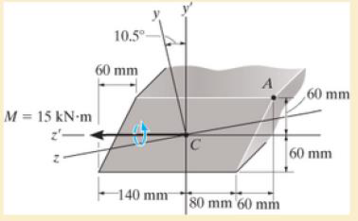
For the section, lz’ = 31.7(10-5) m4, lY’ = 114(10-5) m4, Iy,z' = -15.8(10-6) m4. Using the techniques outlined in Appendix A, the member’s cross-sectional area has principal moments of inertia of lz = 28.8(10-6) m4 and ly = 117(10-6) m4, calculated about the principal axes of inertia y and z, respectively. If the section is subjected to the moment M = 15 kN · m, determine the stress at point A using Eq. 6-17.
Expert Solution & Answer
Want to see the full answer?
Check out a sample textbook solution
Students have asked these similar questions
CORRECT AND DETAILED HANDWRITTEN SOLUTION WITH FBD ONLY. I WILL UPVOTE THANK YOU. CORRECT ANSWER IS ALREADY PROVIDED.
12: A steel cantilever beam 16 ft 8 in in length is subjected to a concentrated load of 320 lb acting at the freeend of the bar. A commercially available rolled steel section, designated as W12x32, is used for the beam. Assume that the total depth of the beam is 12 in, and the neutral axis of the section is in the middle. Determine the maximum tensile and compressive stresses. (Properties of commercially available rolled steel section provided in the table. Z = section modulus). ANS: σT = σC = 1,572.482 lb/in2
CORRECT AND DETAILED HANDWRITTEN SOLUTION WITH FBD ONLY. I WILL UPVOTE THANK YOU. CORRECT ANSWER IS ALREADY PROVIDED.
14: Two ½-in x 8-in cover plates are welded to two channels 10 in high to formthe cross section of the beam shown in Fig. 8-59. Loads are in a vertical plane and bendingtakes place about a horizontal axis. The moment of inertia of each channel about ahorizontal axis through the centroid is 78.5 in4. If the maximum allowable elastic bendingstress is 18,000 lb/in2, determine the maximum bending moment that may be developedin the beam.ANS: 1,236,000 lb-in.
CORRECT AND DETAILED HANDWRITTEN SOLUTION WITH FBD ONLY. I WILL UPVOTE THANK YOU. CORRECT ANSWER IS ALREADY PROVIDED.
11: A beam of circular cross section is 7 in in diameter. It is simply supported at each end and loaded by twoconcentrated loads of 20,000 lb each, applied 12 in from the ends of the beam. Determine the maximum bending stressin the beam. ANS: σ = 7,127.172 lb/in2
Chapter 6 Solutions
Mechanics of Materials
Ch. 6.2 - and then draw the shear and moment diagrams for...Ch. 6.2 - In each case, express the shear and moment...Ch. 6.2 - In each case, express the shear and moment...Ch. 6.2 - In each case, express the shear and moment...Ch. 6.2 - In each case, draw the shear and moment diagrams...Ch. 6.2 - In each case, draw the shear and moment diagrams...Ch. 6.2 - In each case, draw the shear and moment diagrams...Ch. 6.2 - In each case, draw the shear and moment diagrams...Ch. 6.2 - Prob. 1PCh. 6.2 - Prob. 2P
Ch. 6.2 - Prob. 3PCh. 6.2 - Express the shear and moment in terms of x for 0 ...Ch. 6.2 - Express the internal shear and moment in the...Ch. 6.2 - Draw the shear and moment diagrams for the shaft....Ch. 6.2 - Determine the shear and moment as functions of x,...Ch. 6.2 - Determine the shear and moment as functions of x,...Ch. 6.2 - Determine the shear and moment as functions of x,...Ch. 6.2 - Determine the shear and moment in the double...Ch. 6.2 - Draw the shear and moment diagrams for the...Ch. 6.2 - Draw the shear and moment diagrams for the shaft....Ch. 6.2 - Draw the shear and moment diagrams for the...Ch. 6.2 - Draw the shear and moment diagrams for the...Ch. 6.2 - Draw the shear and moment diagrams for the...Ch. 6.2 - Prob. 16PCh. 6.2 - Draw the shear and moment diagrams for the simply...Ch. 6.2 - Prob. 19PCh. 6.2 - Draw the shear and moment diagrams for the beam.Ch. 6.2 - Draw the shear and moment diagrams for the...Ch. 6.2 - The 150-lb man sits in the center of the boat,...Ch. 6.2 - Prob. 24PCh. 6.2 - Draw the shear and moment diagrams for the beam.Ch. 6.2 - Prob. 26PCh. 6.2 - Draw the shear and moment diagrams for the beam....Ch. 6.2 - Prob. 29PCh. 6.2 - Prob. 30PCh. 6.2 - Prob. 31PCh. 6.2 - Prob. 34PCh. 6.2 - Prob. 35PCh. 6.2 - The beam is used to support a uniform load along...Ch. 6.2 - Prob. 39PCh. 6.2 - Prob. 42PCh. 6.2 - Prob. 43PCh. 6.2 - Prob. 44PCh. 6.2 - Prob. 45PCh. 6.2 - The truck is to be used to transport the concrete...Ch. 6.4 - If the beam is subjected to a bending moment of M...Ch. 6.4 - If the beam is subjected to a bending moment of M...Ch. 6.4 - If the beam is subjected to a bending moment of M...Ch. 6.4 - If the beam is subjected to a bending moment of M...Ch. 6.4 - If the beam is subjected to a bending moment of M...Ch. 6.4 - Determine the moment M that will produce a maximum...Ch. 6.4 - Determine the maximum tensile and compressive...Ch. 6.4 - The beam is constructed from four pieces of wood,...Ch. 6.4 - The beam is constructed from four pieces of wood,...Ch. 6.4 - The beam is made from three boards nailed together...Ch. 6.4 - The beam is made from three boards nailed together...Ch. 6.4 - Prob. 54PCh. 6.4 - The tubular shaft is supported by a smooth thrust...Ch. 6.4 - Prob. 57PCh. 6.4 - If the beam is subjected to an internal moment or...Ch. 6.4 - If the beam is made of material having an...Ch. 6.4 - Prob. 60PCh. 6.4 - Prob. 61PCh. 6.4 - The beam is subjected to a moment of M = 40 kN m....Ch. 6.4 - The steel shaft has a diameter of 2 in. It is...Ch. 6.4 - Determine the dimension a of a beam having a...Ch. 6.4 - A shaft is made of a polymer having an elliptical...Ch. 6.4 - Solve Prob. 6-65 if the moment M = 50 N m is...Ch. 6.4 - Prob. 67PCh. 6.4 - If M=4kipft , determine the resultant force the...Ch. 6.4 - The strut on the utility pole supports the cable...Ch. 6.4 - The pin is used to connect the three links...Ch. 6.4 - Prob. 75PCh. 6.4 - A timber beam has a cross section which is...Ch. 6.4 - If the beam is subjected to an internal moment of...Ch. 6.4 - If the allowable tensile and compressive stress...Ch. 6.4 - If the beam is subjected to an internal moment of...Ch. 6.4 - Prob. 80PCh. 6.4 - Prob. 81PCh. 6.4 - Prob. 82PCh. 6.4 - Prob. 83PCh. 6.4 - If the intensity of the load w=15kN/m , determine...Ch. 6.4 - Prob. 85PCh. 6.4 - Determine the absolute maximum bending stress in...Ch. 6.4 - Prob. 87PCh. 6.4 - Prob. 88PCh. 6.4 - If the compound beam in Prob. 642 has a square...Ch. 6.4 - If the beam in Prob. 628 has a rectangular cross...Ch. 6.4 - Determine the absolute maximum bending stress in...Ch. 6.4 - Determine, to the nearest millimeter, the smallest...Ch. 6.4 - If the beam in Prob.63 has a rectangular cross...Ch. 6.4 - The simply supported truss is subjected to the...Ch. 6.4 - If d = 450 mm, determine the absolute maximum...Ch. 6.4 - If the allowable bending stress is allow = 6 MPa,...Ch. 6.4 - Prob. 102PCh. 6.4 - Prob. 103PCh. 6.5 - Determine the bending stress at corners A and B....Ch. 6.5 - Determine the maximum bending stress in the beams...Ch. 6.5 - The member has a square cross section and is...Ch. 6.5 - The member has a square cross section and is...Ch. 6.5 - Consider the general case of a prismatic beam...Ch. 6.5 - The steel shaft is subjected to the two loads. If...Ch. 6.5 - The 65-mm-diameter steel shaft is subjected to the...Ch. 6.5 - For the section, lz = 31.7(10-5) m4, lY =...Ch. 6.5 - For the section, lz, = 31.7(10-5) m4, lY =...Ch. 6.9 - The composite beam is made of steel (A) bonded to...Ch. 6.9 - The composite beam is made of steel (A) bonded to...Ch. 6.9 - Segment A of the composite beam is made from...Ch. 6.9 - Segment A of the composite beam is made from...Ch. 6.9 - A wood beam is reinforced with steel straps at its...Ch. 6.9 - The composite beam is made of A-36 steel (A)...Ch. 6.9 - The composite beam is made of A-36 steel (A)...Ch. 6.9 - If the beam is subjected to a moment of M = 45 kN...Ch. 6.9 - The Douglas Fir beam is reinforced with A-36 steel...Ch. 6.9 - For the curved beam in Fig. 640a, show that when...Ch. 6.9 - The curved member is subjected to the moment of M...Ch. 6.9 - The curved member is made from material having an...Ch. 6.9 - If P = 3 kN, determine the bending stress at...Ch. 6.9 - If the maximum bending stress at section a-a is...Ch. 6.9 - The elbow of the pipe has an outer radius of 0.75...Ch. 6.9 - The curved bar used on a machine has a rectangular...Ch. 6.9 - The steel rod has a circular cross section. If it...Ch. 6.9 - Prob. 150PCh. 6.9 - Prob. 151PCh. 6.9 - The bar has a thickness of 1 in. and the allowable...Ch. 6.9 - The bar has a thickness of 1 in. and is subjected...Ch. 6.9 - Prob. 154PCh. 6.9 - The bar is subjected to a moment of M=17.5Nm If...Ch. 6.9 - Prob. 156PCh. 6.9 - Prob. 157PCh. 6.10 - The beam is made of an elastic plastic material...Ch. 6.10 - The wide-flange member is made from an elastic...Ch. 6.10 - The rod has a circular cross section. If it is...Ch. 6.10 - The rod has a circular cross section. If it is...Ch. 6.10 - The beam is made of an elastic perfectly plastic...Ch. 6.10 - Determine the plastic moment Mp that can be...Ch. 6.10 - Prob. 164PCh. 6.10 - Prob. 166PCh. 6.10 - Prob. 170PCh. 6.10 - Prob. 171PCh. 6.10 - The box beam is made of an elastic perfectly...Ch. 6.10 - The plexiglass bar has a stress-strain curve that...Ch. 6 - Determine the shape factor for the wide-flange...Ch. 6 - The compound beam consists of two segments that...Ch. 6 - The composite beam consists of a wood core and two...Ch. 6 - If it resists a moment of M = 125 N m, determine...Ch. 6 - Determine the maximum bending stress in the handle...Ch. 6 - The curved beam is subjected to a bending moment...Ch. 6 - Determine the shear and moment in the beam as...Ch. 6 - A wooden beam has a square cross section as shown...Ch. 6 - Draw the shear and moment diagrams for the shaft...Ch. 6 - The strut has a square cross section a by a and is...
Additional Engineering Textbook Solutions
Find more solutions based on key concepts
What types of coolant are used in vehicles?
Automotive Technology: Principles, Diagnosis, And Service (6th Edition) (halderman Automotive Series)
The solid steel shaft AC has a diameter of 25 mm and is supported by smooth bearings at D and E. It is coupled ...
Mechanics of Materials (10th Edition)
Assume a telephone signal travels through a cable at two-thirds the speed of light. How long does it take the s...
Electric Circuits. (11th Edition)
This optional Google account security feature sends you a message with a code that you must enter, in addition ...
SURVEY OF OPERATING SYSTEMS
17–1C A high-speed aircraft is cruising in still air. How does the temperature of air at the nose of the aircra...
Thermodynamics: An Engineering Approach
How are relationships between tables expressed in a relational database?
Modern Database Management
Knowledge Booster


Learn more about
Need a deep-dive on the concept behind this application? Look no further. Learn more about this topic, mechanical-engineering and related others by exploring similar questions and additional content below.Similar questions
- using the theorem of three moments, find all the reactions and supportsarrow_forward(An ellipsoidal trapping region for the Lorenz equations) Show that there is a certain ellipsoidal region E of the form rx2 + σy2 + σ(z − 2r)2 ≤ C such that all trajectories of the Lorenz equations eventually enter E and stay in there forever. For a much stiffer challenge, try to obtain the smallest possible value of C with this property.arrow_forwardA) In a factory, an s-type pitot tube was used to calculate the velocity of dry air for a point inside a stack. Calculate the velocity at that point (ft/sec) using following conditions: ● • • Pressure = 30.23 ± 0.01 in Hg (ambient) Pitot tube coefficient = 0.847 ± 0.03 Temperature = 122 ± 0.1 F (stack) Temperature = 71.2 ± 0.1 F (ambient) AP = 0.324 ± 0.008 in H2O (pitot tube) • AP = 0.891 ± 0.002 in H2O (stack) B) Find the dominant error(s) when determining precision for the problem. C) For part A, what is the precision in ft/sec for the velocity?arrow_forward
- Q1/ For what value of x do the power series converge: 8 (-1)n-1. x2n-1 2n-1 x3 x5 = X n=1 3 Q2/ Find the Interval of convergence and Radius of convergence of the series: 8 n Σ 3+1 n=1 (x)"arrow_forwardExample-1: l D A uniform rotor of length 0.6 m and diameter 0.4 m is made of steel (density 7810 kg/m³) is supported by identical short bearings of stiffness 1 MN/m in the horizontal and vertical directions. If the distance between the bearings is 0.7 m, determine the natural frequencies and plot whirl speed map. Solution: Barrow_forwardfind the laplace transform for the flowing function 2(1-e) Ans. F(s)=- S 12) k 0 Ans. F(s)= k s(1+e) 0 a 2a 3a 4a 13) 2+ Ans. F(s)= 1 s(1+e") 3 14) f(t)=1, 0arrow_forwardFind the solution of the following Differential Equations Using Laplace Transforms 1) 4y+2y=0. y(0)=2. y'(0)=0. 2) y+w²y=0, (0)=A, y'(0)=B. 3) +2y-8y 0. y(0)=1. y'(0)-8. 4)-2-3y=0, y(0)=1. y'(0)=7. 5) y-ky'=0, y(0)=2, y'(0)=k. 6) y+ky'-2k²y=0, y(0)=2, y'(0) = 2k. 7) '+4y=0, y(0)=2.8 8) y+y=17 sin(21), y(0)=-1. 9) y-y-6y=0, y(0)=6, y'(0)=13. 10) y=0. y(0)=4, y' (0)=0. 11) -4y+4y-0, y(0)=2.1. y'(0)=3.9 12) y+2y'+2y=0, y(0)=1, y'(0)=-3. 13) +7y+12y=21e". y(0)=3.5. y'(0)=-10. 14) "+9y=10e". y(0)=0, y'(0)=0. 15) +3y+2.25y=91' +64. y(0)=1. y'(0) = 31.5 16) -6y+5y-29 cos(2t). y(0)=3.2, y'(0)=6.2 17) y+2y+2y=0, y(0)=0. y'(0)=1. 18) y+2y+17y=0, y(0)=0. y'(0)=12. 19) y"-4y+5y=0, y(0)=1, y'(0)=2. 20) 9y-6y+y=0, (0)-3, y'(0)=1. 21) -2y+10y=0, y(0)=3, y'(0)=3. 22) 4y-4y+37y=0, y(0)=3. y'(0)=1.5 23) 4y-8y+5y=0, y(0)=0, y'(0)=1. 24) ++1.25y-0, y(0)=1, y'(0)=-0.5 25) y 2 cos(r). y(0)=2. y'(0) = 0. 26) -4y+3y-0, y(0)=3, y(0) 7. 27) y+2y+y=e y(0)=0. y'(0)=0. 28) y+2y-3y=10sinh(27), y(0)=0. y'(0)=4. 29)…arrow_forwardAuto Controls A union feedback control system has the following open loop transfer function where k>0 is a variable proportional gain i. for K = 1 , derive the exact magnitude and phase expressions of G(jw). ii) for K = 1 , identify the gaincross-over frequency (Wgc) [where IG(jo))| 1] and phase cross-overfrequency [where <G(jw) = - 180]. You can use MATLAB command "margin" to obtain there quantities. iii) Calculate gain margin (in dB) and phase margin (in degrees) ·State whether the closed-loop is stable for K = 1 and briefly justify your answer based on the margin . (Gain marginPhase margin) iv. what happens to the gain margin and Phase margin when you increase the value of K?you You can use for loop in MATLAB to check that.Helpful matlab commands : if, bode, margin, rlocus NO COPIED SOLUTIONSarrow_forwardThe 120 kg wheel has a radius of gyration of 0.7 m. A force P with a magnitude of 50 N is applied at the edge of the wheel as seen in the diagram. The coefficient of static friction is 0.3, and the coefficient of kinetic friction is 0.25. Find the acceleration and angular acceleration of the wheel.arrow_forwardAuto Controls Using MATLAB , find the magnitude and phase plot of the compensators NO COPIED SOLUTIONSarrow_forward4-81 The corner shown in Figure P4-81 is initially uniform at 300°C and then suddenly exposed to a convection environment at 50°C with h 60 W/m². °C. Assume the = 2 solid has the properties of fireclay brick. Examine nodes 1, 2, 3, 4, and 5 and deter- mine the maximum time increment which may be used for a transient numerical calculation. Figure P4-81 1 2 3 4 1 cm 5 6 1 cm 2 cm h, T + 2 cmarrow_forwardAuto Controls A union feedback control system has the following open loop transfer function where k>0 is a variable proportional gain i. for K = 1 , derive the exact magnitude and phase expressions of G(jw). ii) for K = 1 , identify the gaincross-over frequency (Wgc) [where IG(jo))| 1] and phase cross-overfrequency [where <G(jw) = - 180]. You can use MATLAB command "margin" to obtain there quantities. iii) Calculate gain margin (in dB) and phase margin (in degrees) ·State whether the closed-loop is stable for K = 1 and briefly justify your answer based on the margin . (Gain marginPhase margin) iv. what happens to the gain margin and Phase margin when you increase the value of K?you You can use for loop in MATLAB to check that.Helpful matlab commands : if, bode, margin, rlocus NO COPIED SOLUTIONSarrow_forwardarrow_back_iosSEE MORE QUESTIONSarrow_forward_ios
Recommended textbooks for you
 Mechanics of Materials (MindTap Course List)Mechanical EngineeringISBN:9781337093347Author:Barry J. Goodno, James M. GerePublisher:Cengage Learning
Mechanics of Materials (MindTap Course List)
Mechanical Engineering
ISBN:9781337093347
Author:Barry J. Goodno, James M. Gere
Publisher:Cengage Learning
Everything About COMBINED LOADING in 10 Minutes! Mechanics of Materials; Author: Less Boring Lectures;https://www.youtube.com/watch?v=N-PlI900hSg;License: Standard youtube license