
Videos
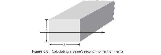
(Statics) A beam’s second moment of inertia, also known as its area moment of inertia, is used to determine its resistance to bending and deflection. For a rectangular beam (see Figure 6.6), the second moment of inertia is given by this formula:
I is the second moment of inertia (m4).
b is the base (m).
h is the height (m).
a. Using this formula, write a function called beamMoment() that accepts two double- precision numbers as parameters (one for the base and one for the height), calculates the corresponding second moment of inertia, and displays the result.
b. Include the function written in Exercise 4a in a working
Want to see the full answer?
Check out a sample textbook solution
Chapter 6 Solutions
C++ for Engineers and Scientists


- Ensure you answer the question asked at the end of the document. Do not just paste things without the GNS3 console outputsarrow_forward"Do not use AI tools. Solve the problem by hand on paper only and upload a photo of your handwritten solution."arrow_forward"Do not use AI tools. Solve the problem by hand on paper only and upload a photo of your handwritten solution."arrow_forward
- "Do not use AI tools. Solve the problem by hand on paper only and upload a photo of your handwritten solution."arrow_forward"Do not use AI tools. Solve the problem by hand on paper only and upload a photo of your handwritten solution."arrow_forwardSolve this "Do not use AI tools. Solve the problem by hand on paper only and upload a photo of your handwritten solution."arrow_forward
- "Do not use AI tools. Solve the problem by hand on paper only and upload a photo of your handwritten solution."arrow_forward"Do not use AI tools. Solve the problem by hand on paper only and upload a photo of your handwritten solution."arrow_forwardSpecifications: Part-1Part-1: DescriptionIn this part of the lab you will build a single operation ALU. This ALU will implement a bitwise left rotation. Forthis lab assignment you are not allowed to use Digital's Arithmetic components.IF YOU ARE FOUND USING THEM, YOU WILL RECEIVE A ZERO FOR LAB2!The ALU you will be implementing consists of two 4-bit inputs (named inA and inB) and one 4-bit output (named out). Your ALU must rotate the bits in inA by the amount given by inB (i.e. 0-15).Part-1: User InterfaceYou are provided an interface file lab2_part1.dig; start Part-1 from this file.NOTE: You are not permitted to edit the content inside the dotted lines rectangle. Part-1: ExampleIn the figure above, the input values that we have selected to test are inA = {inA_3, inA_2, inA_1, inA_0} = {0, 1, 0,0} and inB = {inB_3, inB_2, inB_1, inB_0} = {0, 0, 1, 0}. Therefore, we must rotate the bus 0100 bitwise left by00102, or 2 in base 10, to get {0, 0, 0, 1}. Please note that a rotation left is…arrow_forward
 C++ for Engineers and ScientistsComputer ScienceISBN:9781133187844Author:Bronson, Gary J.Publisher:Course Technology Ptr
 Operations Research : Applications and AlgorithmsComputer ScienceISBN:9780534380588Author:Wayne L. WinstonPublisher:Brooks Cole
 Systems ArchitectureComputer ScienceISBN:9781305080195Author:Stephen D. BurdPublisher:Cengage LearningNp Ms Office 365/Excel 2016 I NtermedComputer ScienceISBN:9781337508841Author:CareyPublisher:CengageCOMPREHENSIVE MICROSOFT OFFICE 365 EXCEComputer ScienceISBN:9780357392676Author:FREUND, StevenPublisher:CENGAGE L